When dealing with machinery, it’s essential to know how different elements interact and function together. Identifying the individual components and their roles can significantly improve the efficiency of maintenance and repair tasks. A clear understanding of each part helps in troubleshooting and ensures your equipment works optimally for longer periods.
In this guide, we will walk you through the structure of various mechanical units, breaking down how each section contributes to the overall performance. Whether you’re looking to repair a malfunctioning unit or simply perform routine upkeep, this information will equip you with the knowledge needed to handle the task with confidence.
Identifying components is crucial when attempting to resolve common issues, and knowing where each element fits in can save you time and effort. By visualizing the layout and understanding the function of each section, you can approach maintenance with a clear strategy.
Understanding the Craftsman Compressor Parts
When working with machinery, it’s important to comprehend the distinct components that contribute to its overall function. Each element has a specific purpose, and understanding how they all work together ensures smooth operation and easier troubleshooting. Whether you’re a professional or a hobbyist, being able to identify and assess the individual sections helps you maintain and repair the equipment effectively.
The core units of any mechanical device are designed to perform specific tasks, from power generation to regulating airflow and pressure. Knowing how each part interacts with others can help you pinpoint issues quickly. This knowledge allows you to address problems before they escalate and even perform preventive maintenance that extends the life of your equipment.
By familiarizing yourself with the construction and layout of the system, you gain insight into its design. Whether dealing with a malfunction or performing routine checks, having a visual reference of the main components enables you to approach repairs with confidence and precision.
How to Read a Compressor Parts Diagram
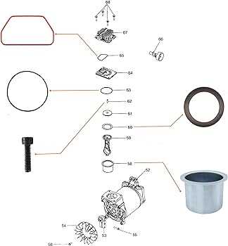
Understanding a visual representation of mechanical components can significantly simplify the maintenance and repair process. Such illustrations show the layout of various elements and how they fit together within the system. Reading these images correctly allows you to identify individual sections, understand their function, and locate potential issues.
To start, it is important to familiarize yourself with the common symbols and conventions used in these illustrations. Manufacturers typically use standardized representations for each element, so recognizing these can make the process much easier. Here’s a step-by-step guide to help you decode the visual references:
- Identify the key components: Look for labels or numbers that represent each section of the system. These usually correspond to part names or catalog numbers.
- Understand the flow of operation: Arrows and lines often indicate how air or power moves through the device, helping you track how each part functions in relation to the others.
- Look for common connections: Pay attention to joints and connections between parts, as these are often the points of failure or wear.
- Use reference guides: Most diagrams are accompanied by a parts list, which matches the numbers or labels from the diagram to specific parts. Keep this list nearby for easy identification.
By following these steps, you will be able to read and interpret the visual layout of the components, allowing for more efficient repairs and maintenance.
Common Issues with Craftsman Compressors
Mechanical systems often encounter a variety of issues over time, with wear and tear being one of the most common causes. Understanding the typical problems that arise in these systems can help you identify and address them before they lead to more serious malfunctions. Many issues stem from specific components or improper maintenance, which can be easily avoided with the right knowledge.
Loss of Pressure

A decrease in pressure is one of the most frequent complaints. This can be caused by several factors, such as leaks in the seals, faulty valves, or improper setup. Regularly checking for air leaks and ensuring the valves are operating correctly can help prevent this issue. If the problem persists, inspecting the connections and replacing worn-out parts may be necessary.
Overheating and Overworking
Another common issue is the system overheating due to overuse or inadequate cooling. If the device runs continuously without proper breaks, it can cause internal components to strain. Cleaning filters and maintaining airflow are essential steps to keep the equipment running smoothly. Additionally, ensuring the motor is not overworked by adjusting usage patterns can extend its lifespan.