Maintaining and repairing your outdoor machinery becomes easier when you have a clear understanding of its inner workings. By learning how different components interact, you can ensure the longevity and proper function of your device. This section will help you visualize and comprehend the specific elements that make up your equipment, providing a structured approach to its care and repair.
By breaking down the essential parts into understandable sections, you can quickly identify any issues that may arise. Whether you’re troubleshooting a malfunction or planning preventive maintenance, knowing the key components will save you time and effort. With a well-organized reference, you’ll be equipped to make informed decisions about repairs and replacements.
Exploring the structure and functions of various sections allows you to approach maintenance tasks with confidence. By using an organized visual guide, you gain a comprehensive overview that helps in diagnosing problems, locating spare parts, and achieving efficient repairs.
Understanding Key Components of Your Equipment
To effectively maintain and repair your machinery, it’s crucial to have a solid understanding of the various elements that make up its structure. Each component plays a specific role in ensuring the overall performance and functionality. In this section, we will examine the essential sections of the device and their functions, helping you gain a clear understanding of what each part contributes.
Familiarizing yourself with these components will allow you to identify issues more efficiently and approach repairs with confidence. Here’s a breakdown of the major components you should know:
- Engine System – This is the powerhouse that drives the entire machinery, providing the necessary power for all operations.
- Transmission Assembly – Responsible for transferring power from the engine to the wheels or other mechanisms, allowing movement and control.
- Fuel System – Ensures that the engine receives the correct amount of fuel for efficient operation and performance.
- Electrical System – Includes the wiring, battery, and other electrical components that manage the flow of electricity to vital areas.
- Steering and Control Mechanisms – These systems ensure proper maneuverability and control, essential for safe operation.
Understanding each of these components allows for quicker identification of issues when they arise. When you know what part does what, you can target the problem more accurately, making repairs more straightforward and cost-effective.
Identifying Key Parts and Functions
Understanding the main components of your equipment and their respective functions is essential for proper maintenance and troubleshooting. Each part serves a distinct purpose, and recognizing how they interact with one another can make repairs or adjustments much more efficient. In this section, we will break down the primary elements and explain their roles in the overall system.
Major Components and Their Functions

Here’s a breakdown of some key sections of the machinery and their specific functions:
| Component | Function |
|---|---|
| Engine | Generates the power required for operation, converting fuel into mechanical energy. |
| Transmission | Transfers power from the engine to the wheels or other mechanisms for movement. |
| Fuel System | Delivers the right amount of fuel to the engine for smooth and efficient operation. |
| Electrical System | Manages the flow of electricity, powering critical functions like the ignition and lighting. |
| Steering System | Controls the direction and movement of the equipment for precise operation. |
Understanding How Parts Work Together
When these components work in sync, the machinery operates smoothly. For instance, the engine generates power that is transmitted to the wheels through the transmission, allowing for movement. The fuel system ensures the engine runs efficiently, while the electrical system powers key components like ignition and lighting. Understanding this interplay will help you diagnose and address issues more quickly.
Step-by-Step Guide to Understanding the Visual Breakdown

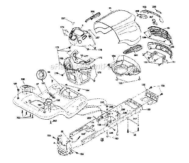
Having a detailed visual guide of your equipment’s components can greatly enhance your ability to maintain and repair it effectively. This section will walk you through how to use such a guide step by step, helping you navigate and interpret the layout of the various parts. With this understanding, you will be able to identify and address issues with greater precision and confidence.
To begin using the visual breakdown effectively, follow these steps:
- Familiarize Yourself with the Layout – Start by reviewing the general layout of the diagram to understand the structure. Look for the different sections that show the device’s primary components.
- Identify Key Components – Locate and identify the major sections like the engine, fuel system, and steering. Each will be labeled clearly, making it easier to spot their location and role.
- Check for Connections – Look for lines or symbols indicating how parts are connected or interact with each other. This is crucial for understanding how the systems work together.
- Note the Part Numbers – Most guides will include reference numbers or labels next to each component. These numbers are helpful when searching for replacement parts or when ordering new ones.
- Use the Guide for Troubleshooting – When issues arise, refer back to the visual guide to locate the faulty components. This can save time by helping you quickly pinpoint the source of the problem.
By following these steps, you will be able to navigate the visual breakdown with ease, making the process of identifying and fixing issues much more straightforward.
How to Use the Visual Guide Effectively
Utilizing a visual reference to understand the structure and function of your equipment can significantly improve the efficiency of your maintenance and repair tasks. Knowing how to read and interpret these references is key to maximizing their potential. This section will provide you with practical steps to make the most of this tool for troubleshooting and servicing your machinery.
To use the visual reference effectively, follow these steps:
- Start with an Overview – Before diving into the specifics, take a moment to familiarize yourself with the general layout. This will help you understand the flow of the system and how various components are interconnected.
- Locate Critical Areas – Focus on identifying the key sections relevant to your task, such as the engine, fuel lines, and steering mechanisms. These are often the most important when diagnosing issues or performing repairs.
- Reference Numbers and Labels – Pay attention to any numbers or labels next to components. These identifiers help you match the visual reference to the actual parts when searching for replacements or discussing issues with a technician.
- Understand Connections – Look for lines or arrows indicating how parts are connected or interact. This is particularly helpful when trying to identify potential issues that might affect multiple components at once.
- Use as a Troubleshooting Tool – When an issue arises, return to the guide to narrow down the source of the problem. The clear layout will allow you to trace where the issue may lie and determine which parts need attention.
By following these steps, you can confidently use the visual guide to address problems and perform maintenance on your equipment efficiently.
Troubleshooting with Visual Reference
When issues arise with your machinery, having a clear reference of its components and how they interact can be invaluable for quick and accurate troubleshooting. This section will guide you through using a detailed visual reference to effectively identify and resolve common problems. By understanding the layout and connections, you can pinpoint malfunctioning parts and take the necessary steps to restore your equipment to full working order.
Follow these steps to troubleshoot using the visual guide:
- Identify the Symptoms – Begin by recognizing the issue at hand. Whether it’s a malfunction in the movement, difficulty starting the machine, or an electrical issue, identifying the problem is the first step in locating the cause.
- Consult the Visual Reference – Once the issue is identified, refer to the visual breakdown. Focus on the sections related to the malfunction, such as the engine or fuel system.
- Trace the Connections – Look for lines or arrows that show how different parts are connected. This can help you identify any broken links or areas that may be causing the problem.
- Check for Damage or Wear – Inspect the specific components highlighted in the reference for any signs of wear, corrosion, or physical damage. These are often the cause of common issues.
- Replace or Repair Components – Once the damaged or faulty component is identified, you can proceed with the necessary repair or replacement, using the reference as a guide for ordering parts and understanding assembly.
By following this process, you can quickly and effectively troubleshoot issues, minimizing downtime and improving the lifespan of your equipment.