Automated systems for home entry offer convenience and security, making daily life easier. These systems consist of various components that work in unison to ensure smooth operation. By understanding the key elements involved, users can troubleshoot issues and improve the functionality of their installations.
Exploring the individual components provides insight into how these systems function. From motorized mechanisms to the sensors that trigger movement, each part plays a crucial role. A thorough understanding helps users maintain the system effectively and prevent common malfunctions.
Familiarizing oneself with these elements empowers homeowners to make informed decisions about repairs and upgrades, ultimately enhancing the longevity and performance of their automated systems.
Understanding Garage Door Opener Components
The functioning of an automated entry system relies on several key elements that must work together seamlessly. These mechanisms and tools, although often unseen, are essential for ensuring smooth and reliable operation. A breakdown or failure in one component can disrupt the entire process, which makes understanding each part crucial for efficient troubleshooting and maintenance.
The Role of the Motor and Mechanisms
The motor acts as the heart of the system, providing the necessary power for movement. It drives the chain, belt, or screw that physically moves the mechanism. This motor is often connected to a system of gears that control the speed and direction of movement, ensuring precision and smooth operation each time the mechanism is activated. Understanding its function helps in diagnosing issues related to power or movement failure.
Control Systems and Safety Features

Modern systems include sensors and remote controls, which allow the user to operate the system from a distance. These control systems ensure that the operation is safe and secure, often stopping movement if an obstruction is detected. Sensors detect objects or motion near the system, preventing potential damage or accidents. Familiarity with how these safety features work ensures the user can properly manage and troubleshoot their system’s performance.
Essential Parts of a Garage Door Opener
Each system designed for automatic home entry relies on several key components to function properly. These elements ensure that the system operates smoothly, responds quickly, and provides the necessary security and convenience. Knowing each critical part helps users maintain the system and address potential issues efficiently.
Drive Mechanism and Motor
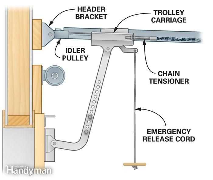
The drive mechanism is responsible for moving the entire assembly. It is powered by a motor that generates the force needed to initiate motion. The motor can be connected to a chain, belt, or screw, depending on the design, and its role is to control the movement speed and direction. Proper functioning of this part ensures that the system operates reliably and without noise.
Sensor and Control Systems
Safety sensors and control systems allow users to operate the mechanism remotely while ensuring security. These sensors detect nearby objects and prevent the system from moving if an obstruction is in the way. Meanwhile, the control systems, often remote or wall-mounted, send signals that control the entire operation, allowing for ease of use and safety during movement.
How to Read a Garage Door Opener Diagram

Understanding a system’s schematic is essential for troubleshooting and maintaining its functionality. These schematics represent the internal connections and relationships between various components. A clear understanding of how to read them ensures you can identify issues quickly and accurately, ultimately leading to more efficient repairs and adjustments.
Identifying Key Components and Their Functions

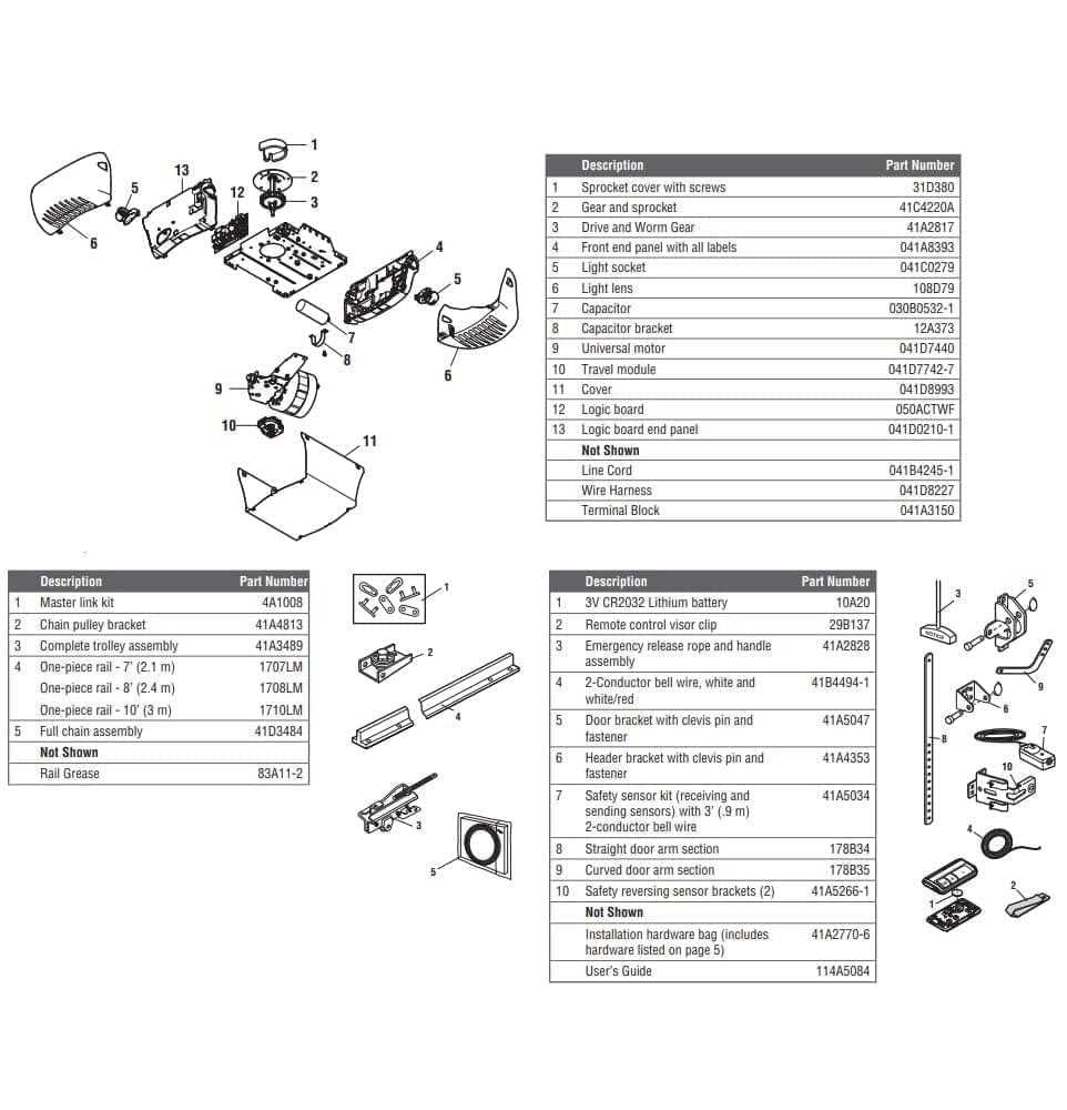
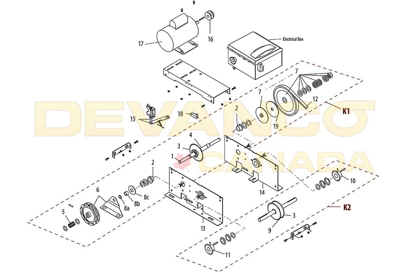
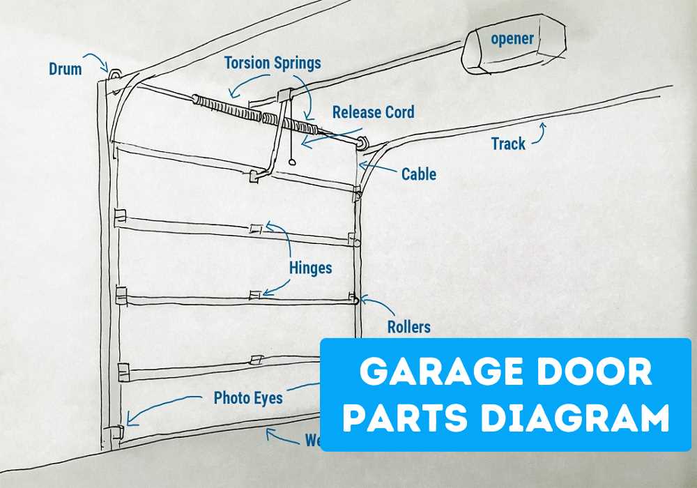
Start by familiarizing yourself with the main elements shown in the schematic. Each component is typically represented by symbols or icons that reflect its physical role in the system. Understanding these symbols allows you to easily follow the layout and locate individual parts, from the power source to the control units, ensuring that you can pinpoint where issues may arise.
Understanding Connections and Flow
The schematic also highlights the connections between different parts of the system. Lines represent electrical or mechanical links, and arrows may indicate the flow of power or movement. By recognizing these connections, you can trace the entire process and understand how each component interacts, helping you troubleshoot or modify the system with confidence.