Every automated entry system consists of various components working in unison to ensure smooth and reliable functioning. From the main control unit to the supporting elements, each piece plays a vital role in the overall operation. Gaining a deeper understanding of how these mechanisms interact can help improve troubleshooting and maintenance skills.
Through a detailed look at the various components, their functions become clearer. Identifying each part within an illustrated guide offers insight into the technical design, allowing users to grasp how motion is generated and controlled. By studying these connections, one can fully appreciate the complexity of such systems.
Key Components of a Garage Door Opener

To ensure smooth and efficient movement, every automated system relies on a set of essential mechanisms. These elements, often hidden within the structure, coordinate to make sure that the process of opening and closing happens seamlessly. Understanding each component’s role can help in both operating and maintaining the system effectively.
Motor and Drive Mechanism

The motor is the core of the system, providing the power necessary to initiate movement. Attached to it is the drive mechanism, responsible for transferring this power to the moving parts. This combination ensures that the system operates reliably over time, with the motor supplying continuous force and the drive translating that energy into motion.
Control Unit and Sensors
The control unit acts as the brain of the system, sending signals to the motor and coordinating the overall operation. Sensors placed at various points monitor the system’s status, ensuring safe functionality. These sensors are crucial for detecting obstacles or irregularities, preventing potential damage or accidents during operation.
How a Garage Door Opener Works

The functionality of an automated entry system revolves around a coordinated interaction of multiple mechanisms. When activated, a series of signals are sent to various components that work together to initiate movement. This process ensures that the system performs its task reliably, whether it’s raising or lowering a barrier, with precision and minimal delay.
The system is activated by a control unit, which processes the signals from a remote or wall-mounted switch. Once the signal is received, the motor engages, driving a mechanism that moves the moving section along its track. Sensors play a crucial role in monitoring the system, ensuring that it functions smoothly and safely throughout its operation. If any obstacles are detected, the sensors send a signal to reverse or halt the movement, protecting both the system and surrounding areas.
Identifying Common Parts in Diagrams

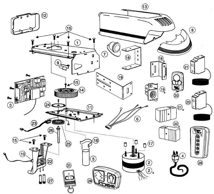
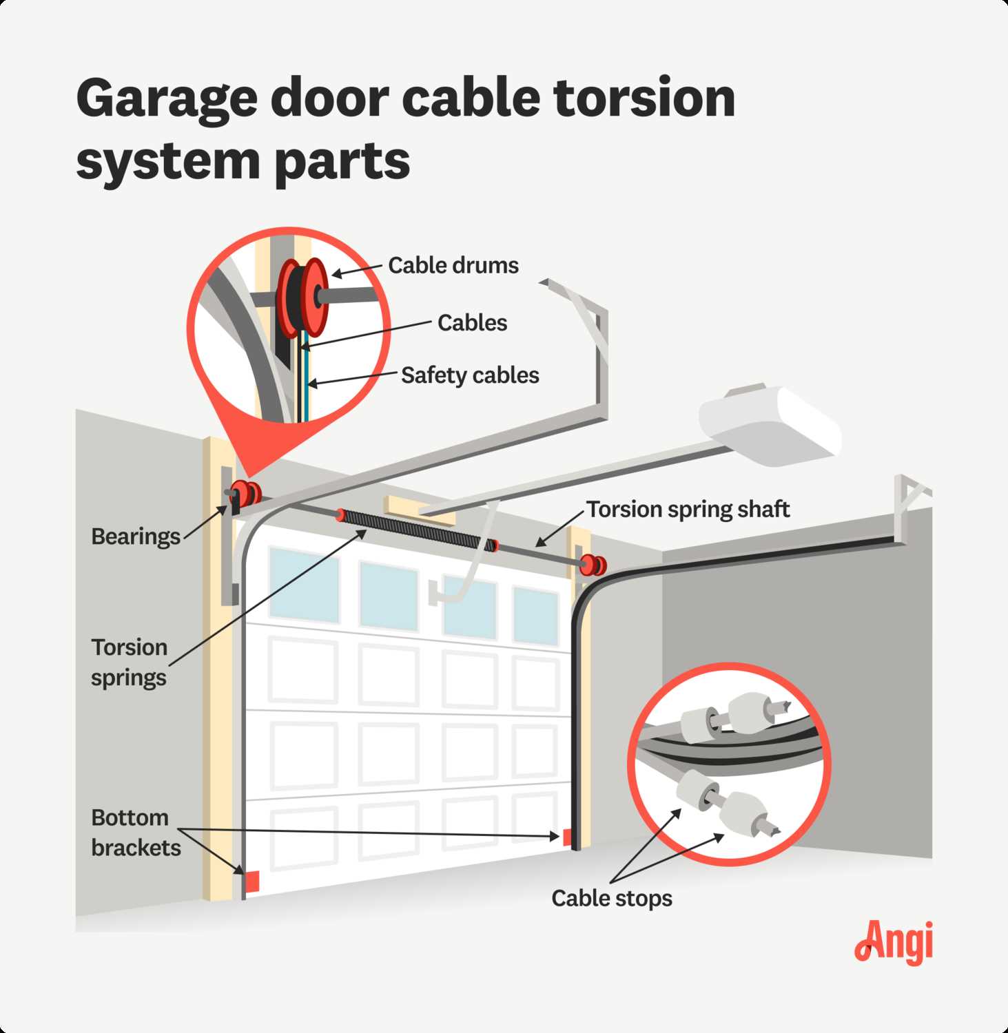
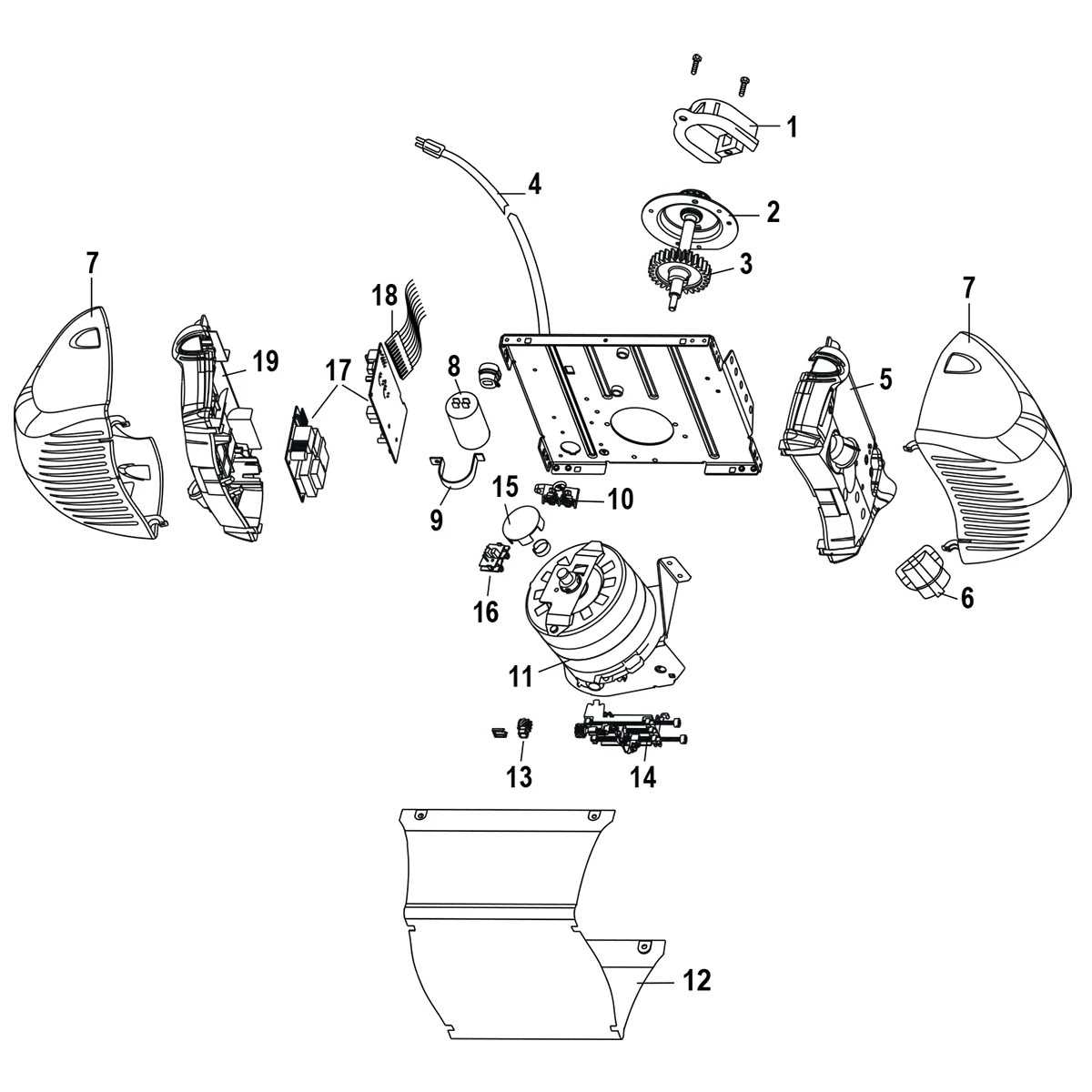
When studying the internal structure of an automated system, recognizing each essential component is crucial for understanding its overall function. These visual representations often break down complex systems into manageable sections, allowing users to pinpoint where each mechanism fits into the broader design. By identifying these common elements, users can gain insight into the system’s operation and troubleshoot effectively.
In most illustrations, key components such as the motor, control unit, and sensors are clearly labeled, each serving a distinct role in the process. The motor is typically depicted as the primary source of power, driving movement through a mechanical mechanism. The control unit is often shown as the brain, processing commands and managing the system’s functions. Sensors, which are integral for safety and efficiency, are also highlighted, demonstrating their role in ensuring smooth operation by detecting any obstacles or malfunctions.