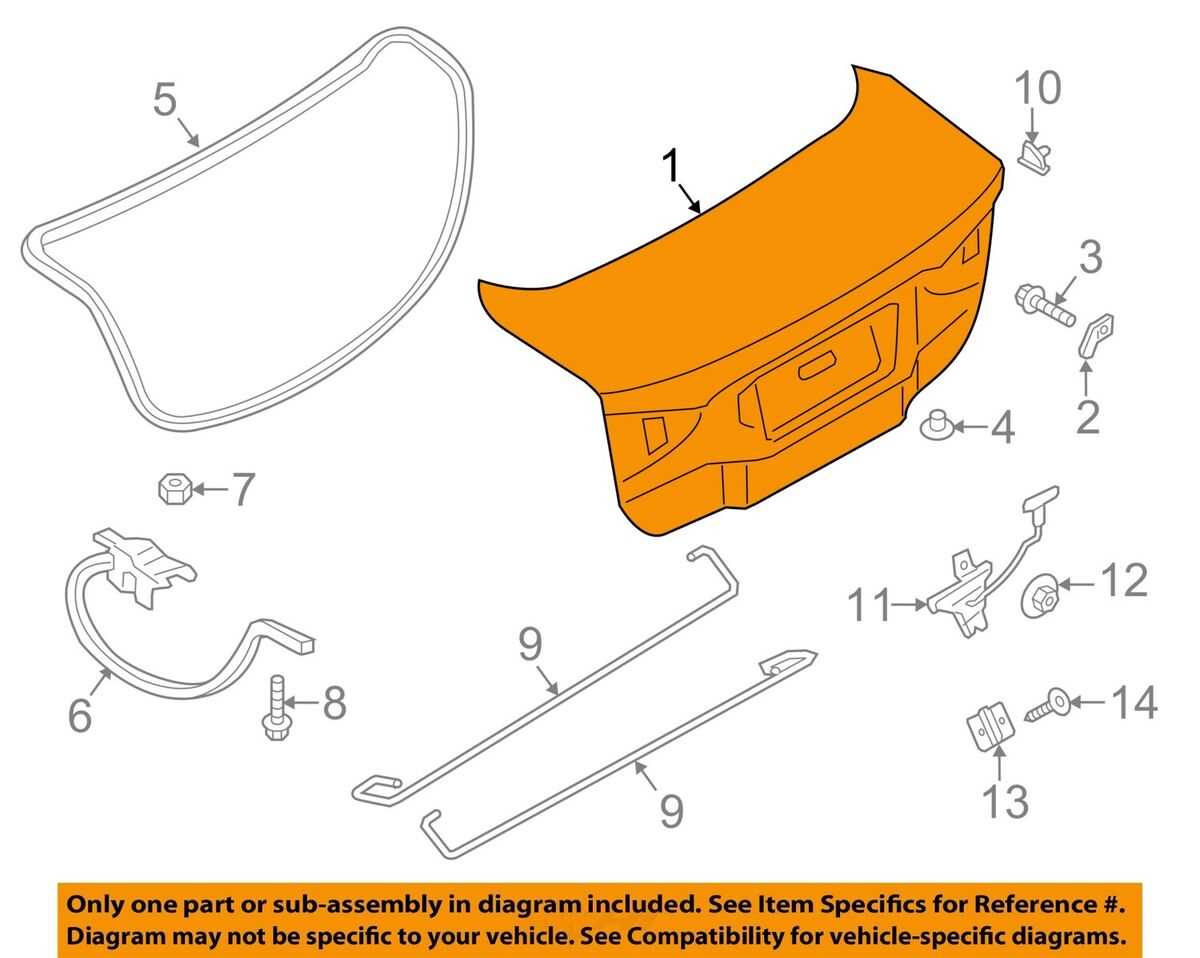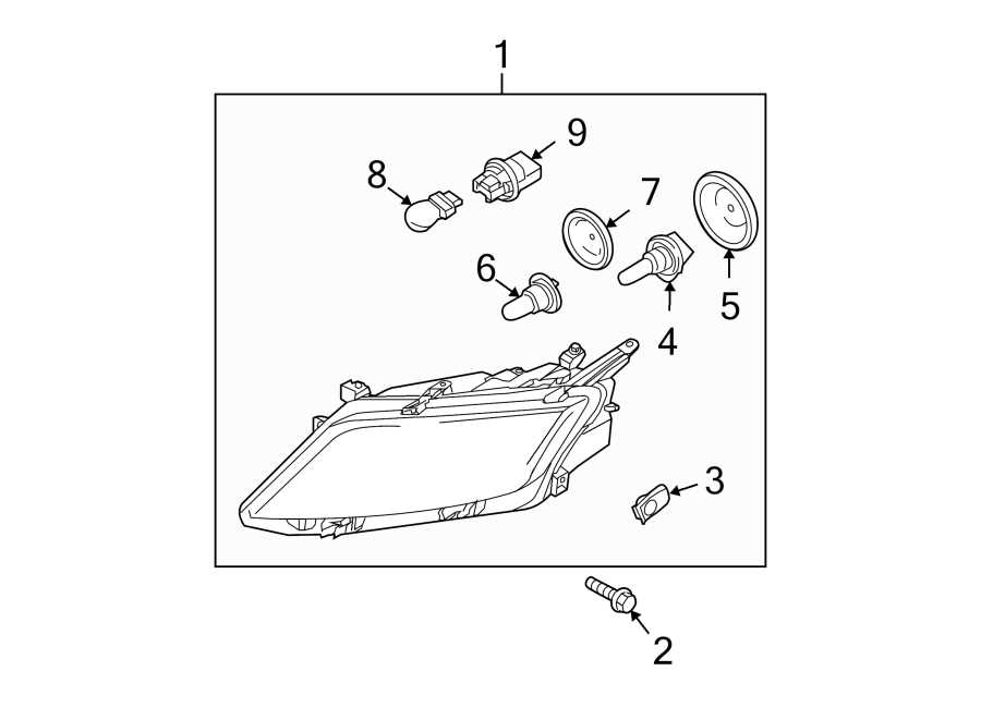
In this guide, we will explore the essential layout of automotive components and their interconnections, providing insight into how each part contributes to the overall performance. Understanding these layouts is crucial for both novice car owners and seasoned mechanics when diagnosing or maintaining a vehicle.
Detailed visual representations allow for a clearer understanding of complex systems within the vehicle. From the engine to the electrical systems, each section of the car is intricately designed to ensure smooth functionality and optimal performance.
By examining these schematics, you gain the ability to identify specific parts and their functions, making repairs and replacements more efficient. The knowledge of systematic arrangements enhances your confidence in handling both minor and major vehicle issues.
Understanding the Vehicle Component Layout
In this section, we will delve into the structure of automotive assemblies, focusing on the importance of visual aids to understand the intricate relationship between different systems. These visual representations offer a detailed view of how individual elements work together, which is crucial for maintaining or repairing a vehicle effectively.
Key Systems and Their Connections
Each vehicle consists of multiple systems, each playing a specific role. By understanding their layout, one can quickly pinpoint any potential issues. The primary systems typically include:
- Engine System: Central to vehicle movement and performance, comprising various components like cylinders, pistons, and fuel injectors.
- Electrical System: Powers the vehicle’s lights, infotainment, and other key functions, including wiring and connectors.
- Suspension System: Ensures comfort and stability by connecting the wheels to the car’s body with parts like shocks and springs.
- Transmission: Transfers power from the engine to the wheels, involving components like the clutch, gearbox, and driveshafts.
How to Interpret Visual Layouts
Reading vehicle component layouts involves understanding the symbols, lines, and structure used to represent each part. It’s important to recognize how different components are interconnected:
- Identify each section: Locate the major systems and familiarize yourself with their function.
- Understand connections: Learn how the parts connect, whether via electrical wiring, fluid systems, or mechanical linkages.
- Follow the flow: Trace how power, fuel, and signals move through the vehicle, helping you understand the overall operation.
With time, this knowledge becomes invaluable when diagnosing issues or making upgrades, allowing for more precise and efficient work.
Key Components in Vehicle Assembly
In any automotive design, understanding the core systems is essential for ensuring smooth operation. These key components are the backbone of the vehicle, responsible for its performance, comfort, and safety. A closer look at these elements can help when diagnosing issues or performing maintenance tasks.
Engine and Powertrain
The heart of any vehicle, the engine and powertrain, work together to produce and transfer power to the wheels. This system includes:
- Engine Block: The main structure housing key components such as cylinders, pistons, and crankshaft.
- Transmission: A system that transmits power from the engine to the wheels, including the gearbox, driveshafts, and clutch.
- Exhaust System: Filters emissions and directs gases safely out of the vehicle.
Chassis and Suspension
The chassis supports the vehicle and holds all other components in place, ensuring the vehicle’s structure remains intact. The suspension system is integral for ride quality and stability, composed of:
- Shocks and Struts: Help absorb road impacts, improving comfort and handling.
- Springs: Provide stability by supporting the weight of the vehicle and maintaining tire contact with the road.
- Control Arms: Help maintain the correct alignment of the wheels and suspension components.
How to Read Vehicle Component Layout

Understanding how to interpret vehicle assembly layouts is essential for efficient repairs and maintenance. These illustrations provide a clear overview of the vehicle’s structure, helping users identify and understand each part’s role within the system. Learning to read these representations empowers you to diagnose issues, replace components, and enhance the vehicle’s performance.
Identifying Key Symbols and Labels
Most automotive layouts include standardized symbols to represent different parts. These symbols make it easier to understand the system’s configuration without needing a detailed knowledge of every component. Common symbols include:
- Lines: Indicate connections, such as electrical wiring or fluid lines, between components.
- Arrows: Show the flow of energy, fluids, or air through the system.
- Shaded areas: Often represent parts that are hidden from view or require removal for access.
Following the Logical Flow
Once the symbols are understood, focus on how the parts are organized. These layouts often follow a logical sequence, showing how power, fluids, or signals move throughout the vehicle. For example:
- Power Transmission: The flow of energy from the engine to the wheels or other systems.
- Cooling System: The movement of coolant through the engine to maintain proper operating temperature.
By following the path laid out in the diagram, users can quickly trace the connection between different components and better understand how to troubleshoot or replace parts.