Understanding the inner workings of a vehicle’s transmission is crucial for anyone interested in its maintenance and repair. This intricate system plays a vital role in ensuring the smooth operation of your vehicle. Proper knowledge of its components can help diagnose issues and improve performance.
In this section, we delve into the essential elements that make up the transmission assembly. By examining these key components, we can gain a deeper appreciation of how they interact to control the vehicle’s movement. A clear understanding of these parts is invaluable for mechanics and car enthusiasts alike.
Accurate identification of each piece is crucial for effective repairs. Recognizing the function and location of each part aids in troubleshooting and ensures a more efficient restoration process. Whether you’re a professional or a hobbyist, knowing these components will enhance your ability to maintain and optimize your vehicle’s performance.
Understanding the Transmission Mechanism
The mechanism behind a vehicle’s transmission system is an essential aspect of its overall performance. It is responsible for ensuring that power from the engine is efficiently transferred to the wheels, enabling smooth operation across different speeds. The way these components work together affects the driving experience, and understanding this system is crucial for anyone looking to maintain or repair a vehicle.
Basic Principles of the System

The system operates through a series of gears and controls that regulate the amount of power delivered to the wheels. By adjusting the gear ratios, the vehicle can manage various speeds and driving conditions. The complexity of these components requires a detailed understanding of how they function and interact.
- Gears: Critical for controlling speed and torque.
- Clutches: Help in smooth engagement and disengagement of gears.
- Shifters: Allow the driver to select different gear settings.
Key Interactions of the System

Each component in the transmission system plays a specific role in ensuring that the vehicle operates smoothly. The interaction between gears, clutches, and control mechanisms creates a dynamic system that adjusts to changing driving conditions. Understanding these interactions allows for a more effective diagnosis of potential issues.
- Gear Synchronization: Ensures that gears shift smoothly without causing damage.
- Torque Distribution: Balances the engine’s power to the wheels efficiently.
- Manual and Automatic Functions: Vary in how they manage gear changes based on the design of the system.
Key Components of the Transmission System
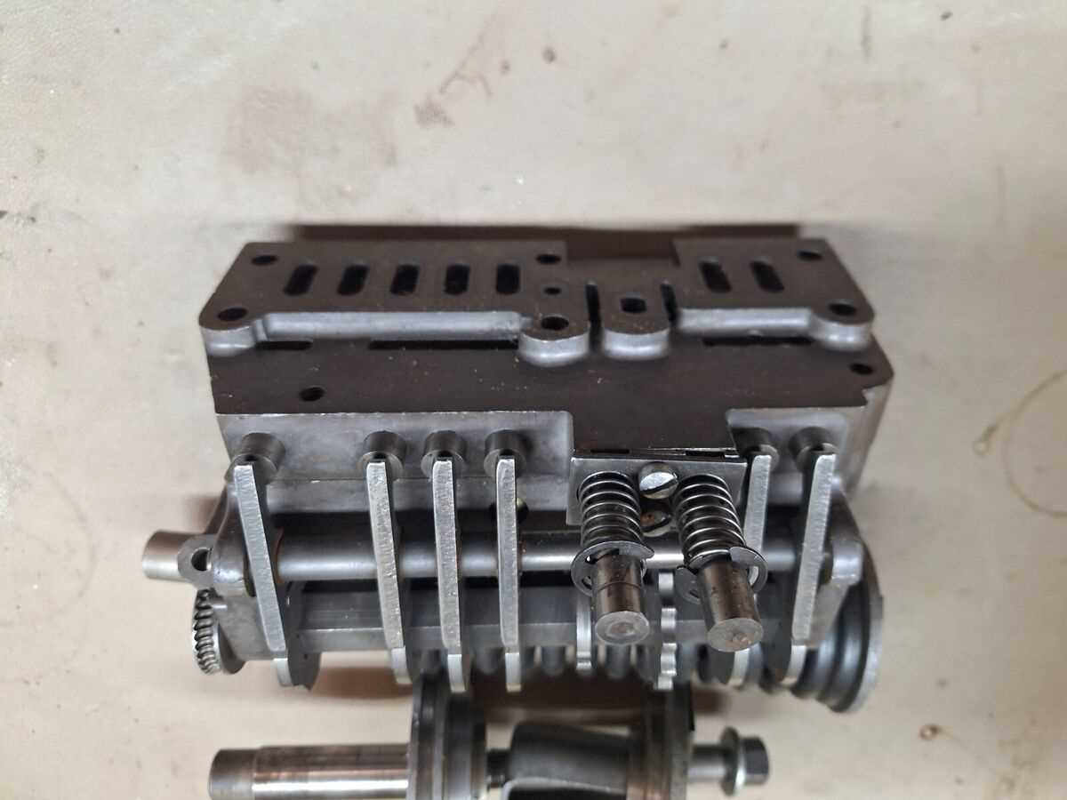
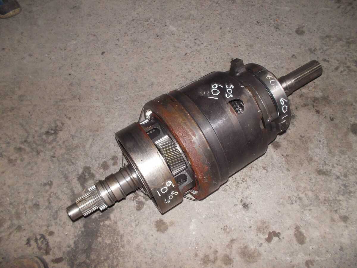
The transmission system consists of various essential elements that work in unison to convert engine power into movement. Each component plays a unique role in ensuring the vehicle shifts seamlessly through different speeds and driving conditions. A solid understanding of these components is necessary for anyone looking to maintain or repair the system efficiently.
Some of the critical components of the transmission include gears, clutches, and control mechanisms. Gears are responsible for adjusting the power output and controlling the vehicle’s speed. Clutches manage the engagement of gears, while the control system allows the driver or vehicle’s automatic system to select the appropriate gear. Together, these elements create a reliable system for smooth operation and efficient power transfer.
When diagnosing or repairing any part of the system, it’s important to understand how each component interacts. Any failure in one part can lead to performance issues and affect the overall functionality of the vehicle. Regular inspection and maintenance of these key elements can prevent breakdowns and ensure optimal performance for years to come.
How to Interpret the Transmission System Layout
Interpreting the layout of a vehicle’s transmission system is an essential skill for understanding how its components are arranged and how they function together. A well-labeled illustration can help identify each element and provide insight into their interactions. By studying these layouts, you can learn how to troubleshoot and maintain the system more effectively.
Understanding the Symbols and Labels
Transmission layouts often use specific symbols and labels to represent various components. Gears, shafts, and other crucial elements are marked clearly, and understanding these symbols helps you identify each part’s role in the system. Look for keys or legends included in the illustration that explain these symbols to avoid confusion.
- Gears: Indicated by simple gearwheel shapes, often with teeth markings.
- Shafts: Represented by long, straight lines with arrows to show direction of movement.
- Clutch Mechanisms: Shown as circular or semi-circular symbols linked to the gears.
Tracing the Flow of Power

Once the components are identified, the next step is understanding how power flows through the system. The layout should show how each component connects and works together. By following the path of energy from the engine to the wheels, you can understand the role of each part in transferring and controlling power.
- Power Input: Typically begins from the engine or motor, shown as an entry point in the layout.
- Power Distribution: Follow the arrows to see how power is distributed across the gears and other components.
- Output: Concludes at the wheels or drivetrain, where the energy is ultimately utilized.