To maintain and troubleshoot any mechanical system, it is crucial to have a clear understanding of its structure and components. Identifying the various elements and how they interact ensures proper functioning and effective repairs. This guide will help you gain insight into the crucial elements of a specific device and how they are organized.
Each part plays a unique role, contributing to the overall performance and efficiency. By familiarizing yourself with the layout, you will be better equipped to address common issues and ensure optimal operation. The following sections will provide you with a breakdown of the system’s key components and how to interpret the detailed layout.
Understanding the System

Every efficient device relies on a series of interconnected components, each contributing to the overall functionality. Understanding how these elements work together is essential for anyone seeking to optimize performance or troubleshoot potential issues. A clear understanding of the internal structure allows for better maintenance and smoother operations over time.
The system in question consists of several crucial units, each designed to fulfill a specific task. From regulating temperature to ensuring safety and efficiency, these elements work in harmony to achieve the desired outcome. Recognizing the function of each component helps in identifying and addressing issues quickly, reducing downtime and enhancing the longevity of the equipment.
Key Components of the Assembly

In any mechanical device, several core elements work together to ensure smooth operation and efficiency. Each unit plays a specific role, contributing to the system’s overall functionality. Understanding these key components is essential for diagnosing issues, performing maintenance, and achieving optimal performance.
The central components in this system include elements responsible for regulating temperature, controlling airflow, and maintaining safety standards. These units are designed to interact seamlessly, allowing for controlled operations and a reliable user experience. Recognizing their function and position within the overall structure is crucial for anyone working with or servicing the equipment.
How to Read the Components Layout
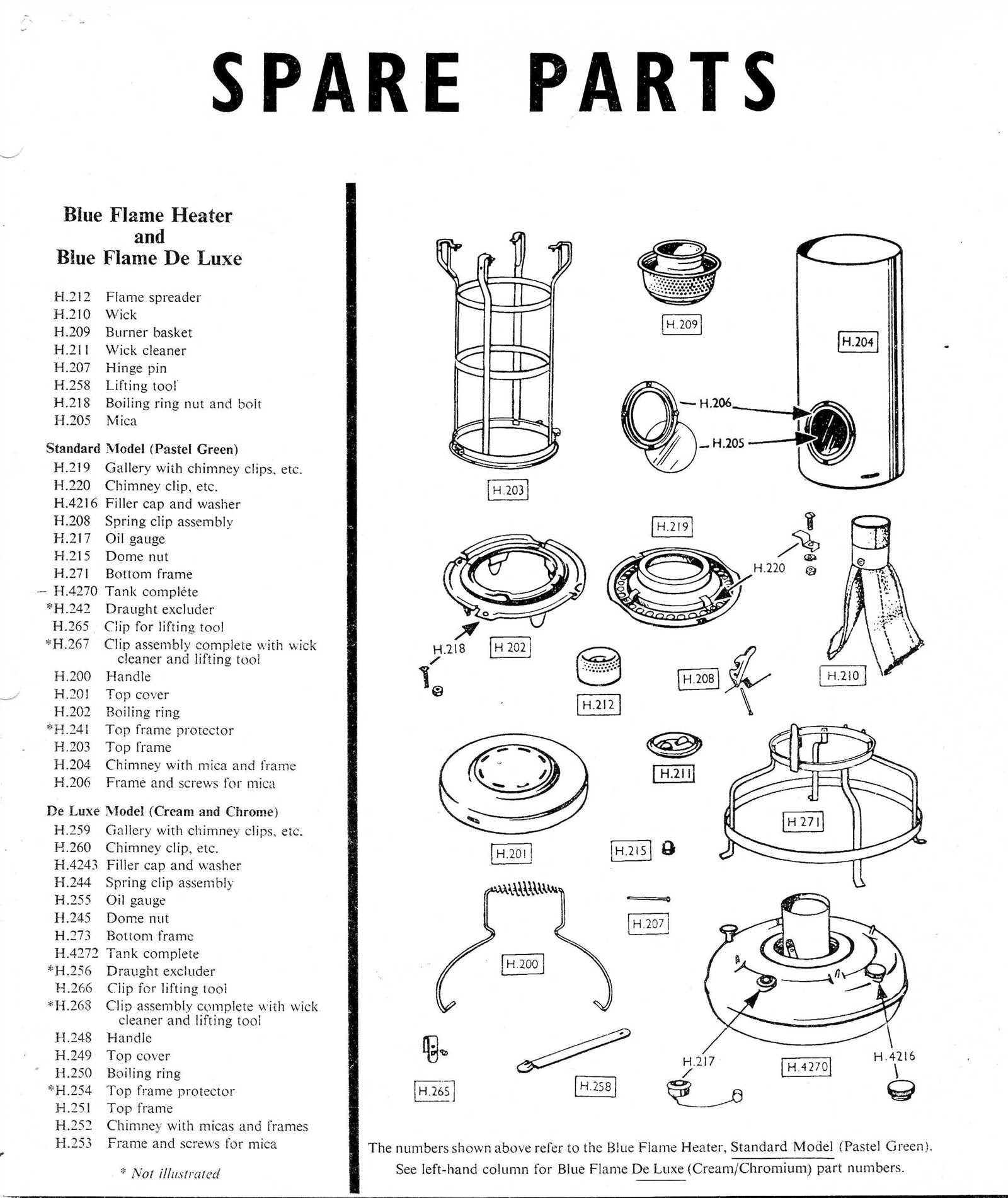
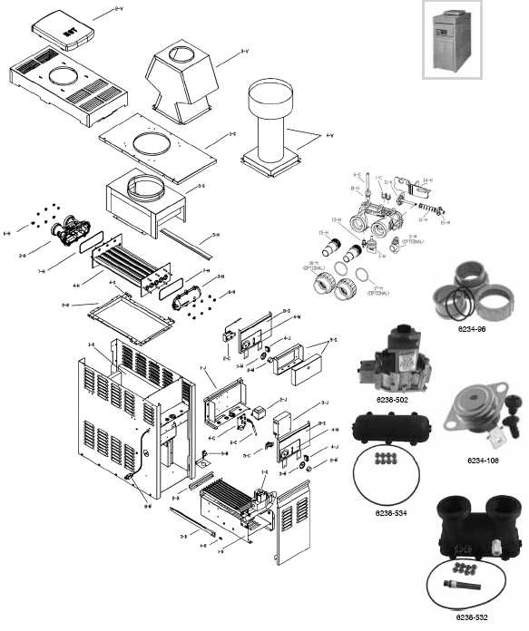
Interpreting a system’s layout requires understanding the relationship between its individual units and their functions. A well-organized map or schematic can guide users in identifying each element’s role, location, and connection to other components. By following this visual guide, it becomes easier to trace issues or plan maintenance tasks effectively.
To begin, focus on the labels and markings that indicate each unit. These references help distinguish between different sections, providing clarity on how they interact. Pay attention to the flow patterns, as they often show how energy or materials move through the system, ensuring proper operation. Understanding these symbols and connections is key to utilizing the layout for troubleshooting and optimization.