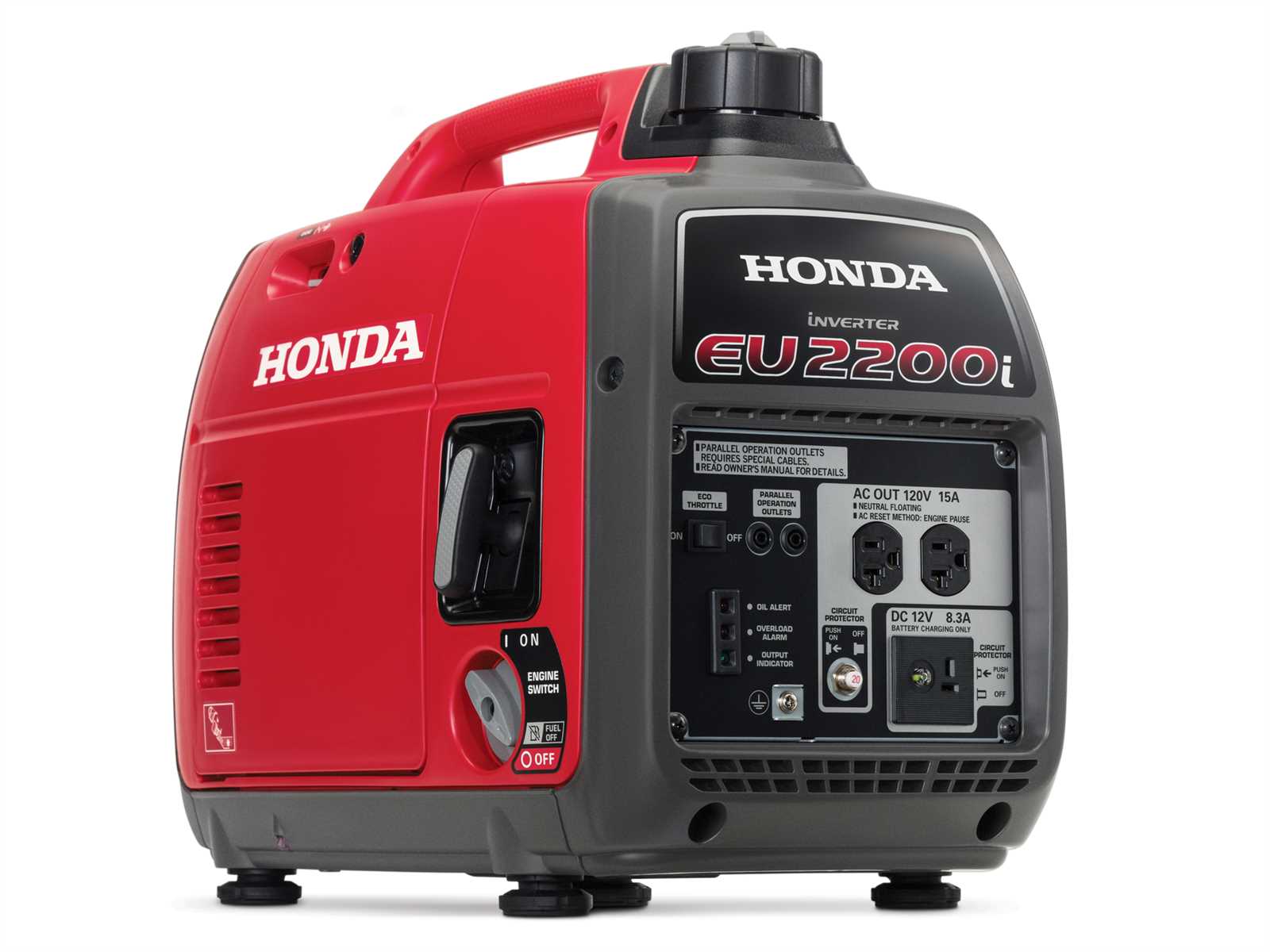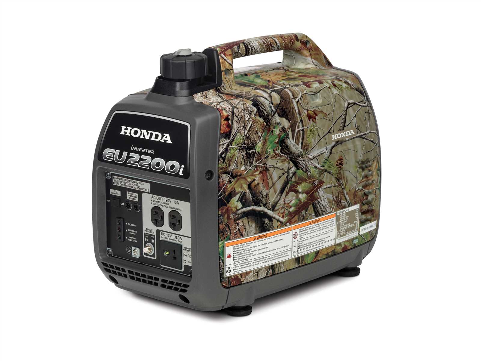
When maintaining or repairing a generator, knowing the layout of its internal and external components is essential. A clear understanding of how the different parts are arranged and interact can save time and prevent costly mistakes. This knowledge helps users identify potential issues and address them before they escalate.
The process of visualizing a generator’s setup involves referring to a detailed schematic that outlines the positions and functions of each individual element. By studying this structure, users can pinpoint the source of any problem more effectively. Whether for routine upkeep or troubleshooting, a well-illustrated map of the system’s components is invaluable for anyone looking to keep their machine in optimal condition.
Mastering the layout of these mechanisms ensures that users are better equipped to perform maintenance tasks with confidence. An in-depth understanding allows for more efficient work, extending the life of the generator and improving its performance over time.
Understanding the Generator Components
To operate and maintain a reliable power source, it’s crucial to have a comprehensive understanding of how its internal mechanisms are organized. The various elements that make up the system each serve a unique purpose, contributing to the overall performance. Familiarity with the setup allows users to quickly identify any malfunctioning part, ensuring efficient repairs and proper upkeep.
Key Elements of the System
The generator consists of several main sections, each designed for specific functions. The engine powers the unit, while the alternator generates electrical output. Other essential components like the fuel system, cooling system, and exhaust system play vital roles in maintaining the machine’s functionality and longevity. Each part interacts with others, forming a cohesive structure that ensures the generator works as intended.
Identifying Common Issues

Understanding the system’s structure helps in diagnosing typical problems. A malfunction in one component can lead to broader issues, making it necessary to pinpoint the faulty part. For instance, a clogged fuel filter or a worn-out spark plug can disrupt performance, and knowing where each part is located makes the troubleshooting process much easier. Regular maintenance and familiarization with the unit’s layout can prevent many common failures.
Key Parts and Functions of the Generator
Every generator consists of a series of essential components that work together to provide reliable power output. Each element serves a distinct role, ensuring the proper function of the system. Understanding how these parts interact is crucial for both troubleshooting and maintenance tasks, helping to optimize the overall performance of the unit.
Power Production Components
The core elements involved in generating electricity are the engine and the alternator. The engine converts fuel into mechanical energy, which is then transferred to the alternator. The alternator, in turn, converts this mechanical energy into electrical power. Together, these components are responsible for creating the electrical output necessary for the generator to function.
Supporting Systems
In addition to the main production units, supporting systems such as the fuel system, cooling system, and exhaust system ensure smooth operation. The fuel system delivers the necessary fuel to the engine, while the cooling system prevents overheating by dissipating excess heat. Meanwhile, the exhaust system directs harmful gases away from the unit, contributing to safe and efficient operation.
How to Read the Generator Schematic

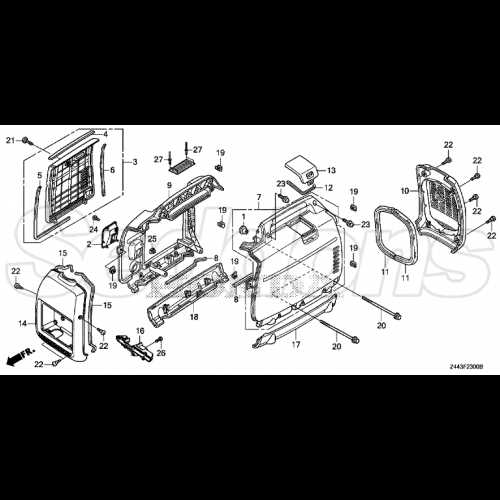
Understanding how to interpret a generator schematic is key to successful troubleshooting and maintenance. A well-detailed schematic visually represents the layout of the system, helping users identify each component and its relationship to the others. By analyzing this schematic, users can more easily pinpoint problems, locate specific parts, and ensure that the unit operates smoothly.
Interpreting the Visual Layout
In most schematics, components are represented by simple icons or drawings, each corresponding to a specific part of the generator. To understand the system, it’s important to familiarize yourself with these symbols and their meaning. For example, the engine may be depicted by a circular symbol, while the alternator could be shown as a set of lines indicating energy flow. These visual cues allow for quick identification and understanding of how each part functions within the system.
Locating and Identifying Components
The schematic typically arranges parts in a logical sequence, from fuel intake to power output. Connecting lines between components illustrate how energy flows and how different parts are linked. Understanding these connections is crucial when performing repairs, as it helps you determine the exact location of a malfunctioning part. Moreover, many diagrams include part numbers, making it easier to order replacements when necessary.