Maintaining and repairing a boat engine requires a clear understanding of its structure and functionality. Having a visual representation of its key elements can significantly ease the process of troubleshooting and maintenance.
Detailed guides are crucial for anyone looking to ensure their motor operates at peak performance. By identifying each component and its purpose, you can more effectively address any issues that may arise during operation.
In this section, we’ll explore the main elements of a boat engine and how to interpret the assembly chart. This knowledge will empower you to make informed decisions when performing repairs or seeking replacement parts.
Understanding 40 HP Marine Engine Components
A deep knowledge of a motor’s components is essential for anyone involved in its upkeep and repair. Recognizing each crucial element allows for better handling of mechanical issues and ensures a smoother boating experience. The internal system consists of various interconnected units, each playing a specific role in overall functionality.
Key Elements of the Motor
Among the most important components are the power system, the cooling mechanism, and the control elements. The power system is responsible for generating force, while the cooling system prevents the engine from overheating during use. The control mechanisms allow the operator to direct the engine’s functions precisely, providing an intuitive user experience on the water.
Maintaining and Troubleshooting

Proper maintenance of each part is crucial to avoid unnecessary repairs and ensure the engine operates efficiently. Regular inspection and understanding of each section will help identify wear and tear or malfunction. Addressing minor issues early can prevent more significant problems down the line, making proactive care an essential part of marine engine management.
Key Components of the Marine Motor

Every boat engine is made up of various essential elements, each designed to serve a specific function in ensuring smooth operation. Understanding these core components helps maintain efficiency and troubleshoot any potential issues that may arise while using the motor.
The power system is the heart of the motor, responsible for generating the force needed to propel the vessel forward. This system includes the engine block, cylinder head, and pistons, which work together to create the necessary power.
The cooling system is equally important, as it prevents overheating by circulating water or coolant through the engine. Key elements of this system include the thermostat, water pump, and cooling passages, which regulate temperature and maintain optimal engine performance.
Finally, the control mechanisms allow the operator to manage the engine’s functions. These include the throttle, shift mechanism, and steering system, ensuring the motor operates according to the user’s commands with precision and ease.
How to Read the Assembly Illustration
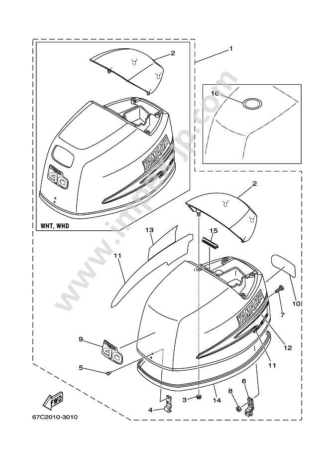
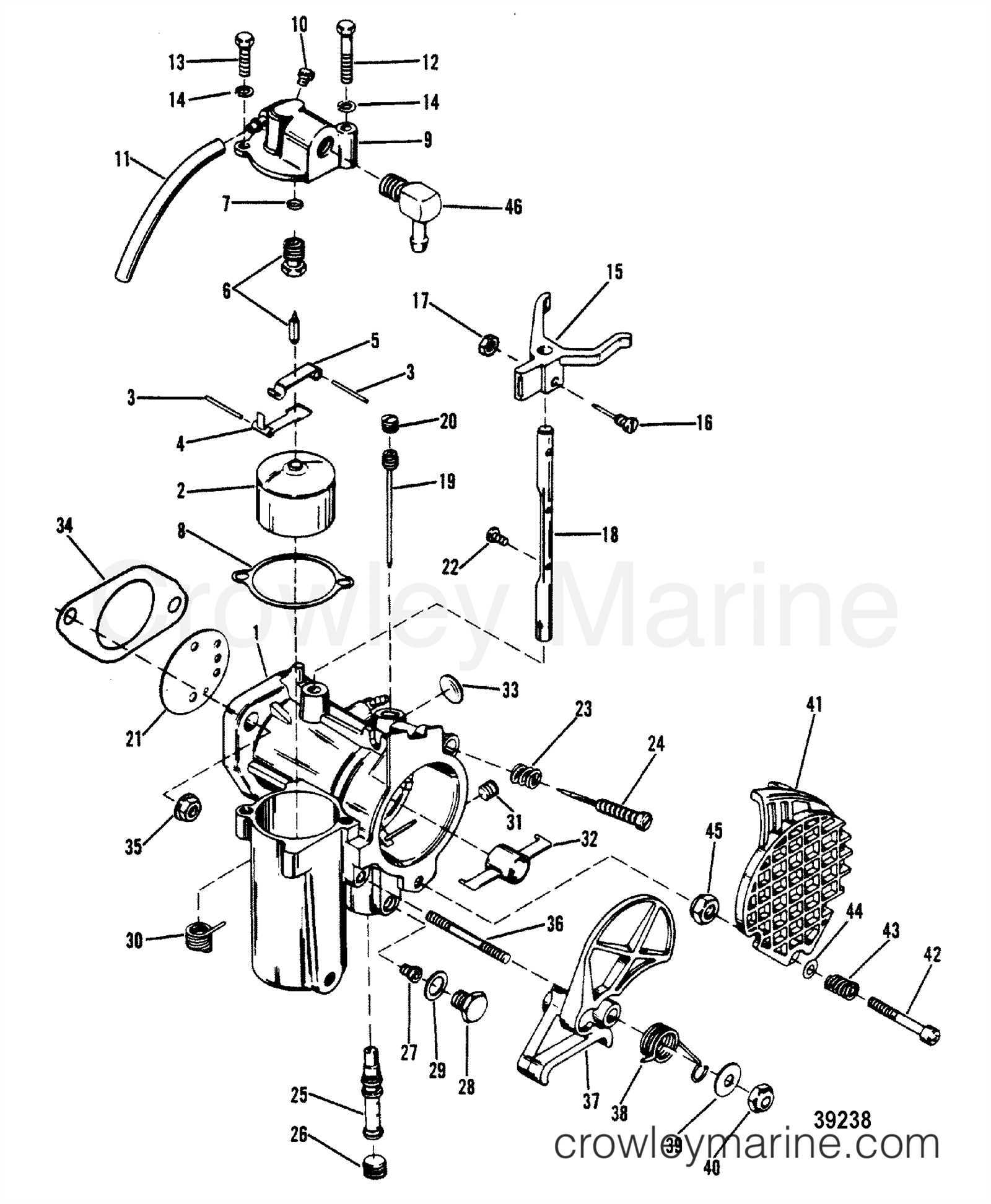
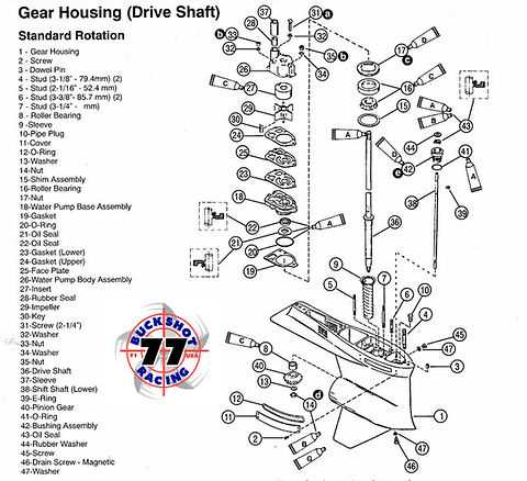
Understanding how to interpret an engine’s schematic is essential for anyone involved in repairs or maintenance. These illustrations provide a clear visual representation of how components fit together and interact. By learning to read them, you can easily locate parts, identify functions, and simplify the process of assembly or disassembly.
Identifying Key Symbols and Labels

One of the first things to look for is the use of symbols and labels that represent various engine components. These symbols act as shorthand, helping you quickly identify key parts without having to refer to lengthy descriptions. Typically, each part will be numbered, and a corresponding list will provide the name or function of the component.
Understanding the Layout and Structure
The schematic will often display the components in a layout that mirrors how they are arranged in the engine. Pay attention to the flow of the illustration, which typically follows the order in which components are assembled. This can help you better understand how the parts connect and interact, making it easier to troubleshoot or replace a malfunctioning component.