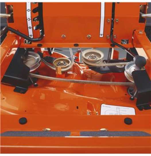
When working with any machinery, knowing how each element functions is essential for proper maintenance and smooth operation. Identifying individual components can help troubleshoot issues and ensure longevity.
Visual aids can greatly enhance the understanding of a machine’s internal workings, simplifying the process of part replacement or adjustment. Knowing how parts connect and interact allows for quicker repairs and efficient operation.
This guide will assist in recognizing key elements of the MZ 54, providing a clear overview of its assembly and helping users identify essential pieces for better maintenance and troubleshooting.
Understanding the MZ 54 Components
To maintain optimal functionality, it is essential to have a clear understanding of the key elements that make up the MZ 54. Each component plays a critical role in the overall operation, and knowing how they work together can significantly ease repair or adjustment procedures.
Key Elements of the Assembly
Within the system, several core components ensure smooth performance. Here are some of the primary sections you should familiarize yourself with:
- Engine – The heart of the machine, responsible for power generation.
- Transmission – Manages power transfer from the engine to the wheels.
- Control System – Includes levers and switches for operation.
- Wheels and Suspension – Supports the machine’s movement and stability.
- Deck – Houses the cutting blades and controls cutting height.
How Components Work Together
The effectiveness of each component depends on how well they interact. For instance, the engine and transmission must work seamlessly to ensure power is delivered smoothly to the wheels, while the deck requires precise adjustments to maintain the cutting quality. Understanding these connections allows for better management and troubleshooting of the machine.
- Proper synchronization between the engine and transmission ensures smooth acceleration and deceleration.
- The cutting deck’s height can be adjusted based on the terrain, making mowing more efficient.
- The control system allows users to make real-time adjustments to power, speed, and movement.
Familiarity with these basic elements is crucial for anyone looking to operate, maintain, or repair the MZ 54 efficiently. By understanding the role each component plays and how they interact, users can enhance their experience and prolong the machine’s lifespan.
Key Components and Their Functions
Understanding the major components of any machine is essential for effective operation and maintenance. Each key element has a specific role that contributes to the overall performance, from providing power to controlling motion. Knowing how these parts work together helps ensure smooth functionality and ease in troubleshooting any issues.
Power and Propulsion Systems
The power and propulsion systems are fundamental to the operation of the machine. These components include:
- Engine – Generates the necessary power to operate all functions, including moving the machine and driving other systems like the cutting mechanism.
- Transmission – Transfers the power from the engine to the wheels, ensuring proper movement and speed control.
- Drive Belts – Help transfer energy from the engine to other components like the cutting deck, ensuring synchronized performance across systems.
Operational and Control Systems
The operational components control the movement, speed, and cutting functions of the machine. These include:
- Control Levers – Allow the user to adjust speed, direction, and cutting height, giving full control over the machine’s operation.
- Cutting Deck – Houses the blades and is responsible for mowing, with adjustable settings to ensure an even cut at different heights.
- Suspension System – Provides stability and shock absorption, ensuring smooth operation even on uneven terrain.
Each of these components works in harmony to deliver the best performance. Understanding their individual functions and interactions allows for more effective troubleshooting, easier repairs, and an overall better user experience.
How to Interpret the Parts Diagram
Understanding how to read technical illustrations is a valuable skill for anyone working with machinery. These visual aids provide clear references for identifying and locating specific components, helping users effectively maintain or repair their equipment. Proper interpretation of these visuals ensures that parts can be replaced accurately and repairs can be done efficiently.
Start by identifying the key sections – most diagrams are divided into specific areas representing different functional groups of the machine. For example, one area might show the engine components, while another illustrates the transmission system. Understanding these divisions allows for quicker navigation when looking for a specific part.
Look for labels and numbers – each part in the illustration will usually be numbered or labeled for easy identification. These identifiers correspond to a parts list, which includes detailed descriptions and additional information about the components. Cross-referencing these numbers ensures the correct part is identified for replacement or maintenance.
- Check for arrows and connections – these show how components interact with one another, providing insight into assembly or disassembly steps.
- Understand the scale – most diagrams include a scale to indicate relative sizes, which can be helpful when ordering replacement parts.
- Pay attention to exploded views – some diagrams provide exploded views that show how parts fit together, which is especially useful for complex systems.
By carefully analyzing these visual representations, users can gain a better understanding of how the machine operates and how to effectively perform maintenance tasks. This knowledge empowers users to take more control over their equipment, ensuring better performance and fewer breakdowns.