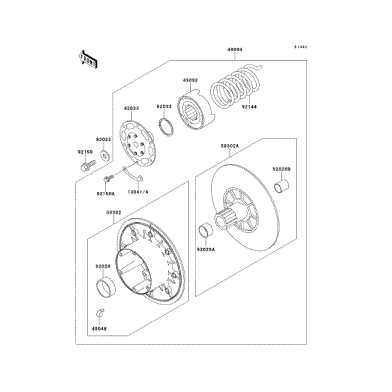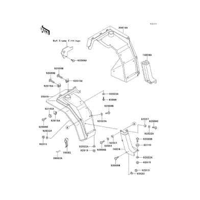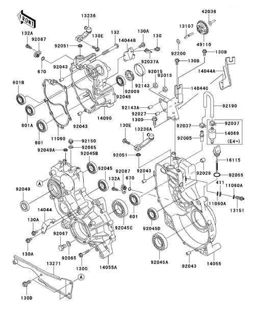
Understanding the intricate details of a utility vehicle is essential for efficient maintenance and repairs. By having a clear view of each individual element, vehicle owners can ensure smooth performance and avoid costly errors. This section aims to provide a visual reference to help you navigate through the various components that make up your vehicle. Whether you are a seasoned mechanic or a first-time owner, having this guide will simplify the process of recognizing each part’s function and importance.
With the right resources, identifying and understanding each piece becomes an easy task. By referring to a well-organized chart, you can quickly pinpoint what needs attention or replacement. This guide serves as a valuable tool for anyone looking to gain a better understanding of the vehicle’s structure and internal workings. Proper knowledge of the layout leads to better decision-making when it comes to repairs and upgrades, ensuring long-term reliability and durability.
Kawasaki Mule 2510 Component Overview
A utility vehicle’s effectiveness relies on a wide range of components, each playing a critical role in its overall performance. Understanding how these individual elements interact allows for better care and maintenance. In this section, we will explore the main sections of the vehicle and provide a closer look at the key features that contribute to its reliability and durability.
Engine and Transmission
The engine is the heart of any vehicle, providing the power needed for movement. Alongside the engine, the transmission ensures that this power is effectively transmitted to the wheels. Understanding the different parts within these systems is crucial for identifying any issues that may arise.
- Engine block and cooling system
- Transmission assembly and gears
- Exhaust system components
- Fuel system and injectors
Suspension and Steering
The suspension and steering systems are vital for providing a smooth ride and precise control. These components allow the vehicle to absorb shocks and maintain stability, ensuring a comfortable and safe experience for the driver and passengers.
- Shock absorbers and struts
- Steering rack and linkages
- Axles and differential
- Wheel hubs and bearings
Understanding the Parts Breakdown

To maintain and repair any utility vehicle, it is crucial to have a comprehensive understanding of its individual components. The breakdown of these elements helps in identifying their specific functions and the role they play in the overall operation of the vehicle. This section will guide you through the process of understanding each segment, allowing for efficient troubleshooting and proper care.
Identifying Core Components

Each vehicle is made up of several key systems, including the engine, transmission, suspension, and electrical components. By understanding how these systems interconnect, it becomes easier to identify issues and determine the right solutions. The components are typically organized into logical groupings for ease of identification.
- Engine components: pistons, crankshaft, cylinder head
- Transmission system: clutch, gear shift mechanism, belts
- Suspension system: springs, shock absorbers, control arms
- Electrical system: alternator, wiring, battery
Common Wear and Tear Areas
Over time, certain components are more prone to wear due to regular use. Understanding which parts tend to degrade faster allows for proactive maintenance, reducing downtime and repair costs. Regular inspection and replacement of these components can keep the vehicle running smoothly.
- Belts and hoses: often need replacing after extended use
- Brakes: pads, rotors, and calipers wear down with frequent stopping
- Tires: must be monitored for tread depth and pressure
How to Use the Parts Diagram Effectively
Having a detailed visual representation of a vehicle’s components can be an invaluable resource when it comes to maintenance and repairs. By learning how to interpret and navigate through the visual guide, you can save time, reduce errors, and ensure proper installation of any replacement elements. This section will walk you through the best practices for making the most out of these visual references.
Step-by-Step Approach
The first step in using any schematic effectively is to familiarize yourself with the layout. Begin by identifying the main systems of the vehicle, such as the engine, transmission, and suspension. Each section of the diagram is usually divided by these categories, making it easier to focus on a specific area.
- Locate the general categories: engine, transmission, electrical, etc.
- Identify individual components within each section
- Study the connections and relationships between parts
Pinpointing Issues and Replacements
Once you’ve understood the basic layout, the next step is to use the diagram to identify damaged or worn-out components. The visual guide can help you quickly locate a specific element and determine its role within the larger system. This makes it easier to plan repairs or replacements without missing crucial parts.
- Look for highlighted or labeled parts that may require attention
- Cross-check with the vehicle’s manual for precise part numbers
- Use the diagram to verify the correct placement of new parts