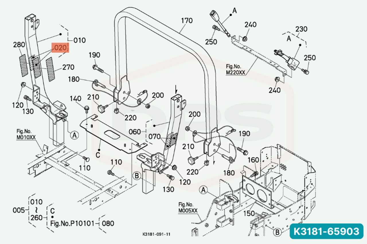
Maintaining a lawn mower requires a clear understanding of its internal structure and the ability to identify different parts. Knowing how each element works together ensures smooth operation and extends the life of the machine. Whether for regular maintenance or repairs, a comprehensive view of the mower’s construction is crucial.
When tackling mechanical issues, having a detailed reference guide becomes invaluable. By studying an organized schematic, you can quickly pinpoint faulty components, make informed decisions about replacements, and prevent unnecessary breakdowns. A well-maintained machine operates more efficiently and with fewer problems, allowing for a hassle-free mowing experience.
Understanding the layout and function of various components also helps in troubleshooting and improving performance. With the right knowledge, even minor issues can be resolved promptly, keeping your mower in top condition for longer periods. A clear reference to how parts are connected and function together is essential for both novice users and seasoned experts.
Understanding the Kubota ZG222 Parts
For any equipment owner, knowing how the internal components work together is essential for efficient operation and long-lasting performance. Each machine consists of several interconnected elements, each with a specific role. Familiarity with these key components ensures better maintenance practices and quicker resolution of issues when they arise.
Key Components and Their Functions
In any machine, several crucial pieces work in harmony to ensure smooth functioning. From the engine to the wheels, each component has a specific task. For instance, the drive system enables mobility, while the cutting mechanism ensures the desired results during operation. By understanding the relationship between these elements, owners can identify potential issues and address them effectively.
Maintaining and Replacing Key Elements

Regular inspection and timely replacement of worn-out components are essential to keep the equipment running efficiently. Knowing which elements are subject to wear allows users to plan for maintenance ahead of time, preventing more significant problems. Using a comprehensive reference to locate and identify parts helps ensure that replacements are made correctly and on time, thus minimizing downtime.
Identifying Key Components in the Diagram
Understanding the layout of a machine and its components is essential for effective maintenance and repair. A detailed schematic can provide a visual guide, helping users quickly locate and identify the most important elements. By familiarizing yourself with the layout, you can efficiently troubleshoot issues and perform necessary repairs with minimal effort.
Locating the Drive and Cutting Systems
The drive and cutting systems are two of the most critical areas to focus on. These components are responsible for the movement and operation of the machine. In the schematic, these elements are often positioned prominently, as they require regular inspection and maintenance. Recognizing their function and placement helps users address any operational issues swiftly.
Identifying Auxiliary Components
In addition to the primary systems, several auxiliary elements support the overall functionality. These may include safety features, electrical connections, and control mechanisms. Understanding where these components are located and their interconnections allows for quicker troubleshooting and more effective repairs, ensuring the machine runs smoothly.
How to Use the Parts Diagram for Repairs
When performing repairs on a machine, having a clear visual guide is invaluable. A well-structured schematic provides users with the necessary information to identify and replace faulty components. By referencing the guide, you can accurately pinpoint the damaged parts and avoid unnecessary disassembly, saving both time and effort.
Step-by-Step Guide for Troubleshooting
To begin repairs, start by examining the schematic and locating the component in question. Focus on the system or area that is malfunctioning, and cross-reference it with the diagram to find its exact position and related parts. This will help in isolating the issue and preventing unnecessary part removal or damage to other elements.
Replacing Components with Confidence
Once the faulty component has been identified, use the schematic to understand how it fits into the larger system. The guide will show how the piece connects with other elements, ensuring that replacements are done correctly. With this visual aid, you can proceed with confidence, knowing that each part will be restored to its proper place for optimal performance.