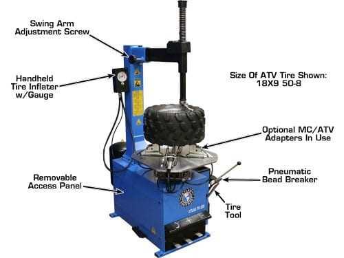
When working with vehicle service tools, it’s essential to grasp how different elements work together to ensure efficiency. Various sections of the equipment play crucial roles in assisting technicians with repairs and adjustments. Knowing how these components fit into the overall structure allows for smoother operations and quicker resolutions during service tasks.
Each piece of the system is designed to contribute to specific functions, from mounting and dismounting to balancing. Understanding the layout and purpose of these parts can prevent operational issues and improve maintenance practices. Familiarity with the equipment’s setup is key to achieving optimal performance in a repair setting.
By familiarizing yourself with the different sections and their functions, you gain insight into the mechanics behind successful repairs. This knowledge enhances the repair process and reduces the likelihood of errors, leading to more efficient service delivery.
Understanding the Key Parts of a Tire Machine
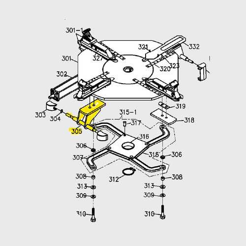
Every tool used in vehicle maintenance consists of multiple elements that function together to achieve specific tasks. These sections, although varied in design and purpose, are essential for completing the process effectively. Whether it involves mounting, balancing, or adjusting, each part works in harmony to streamline operations and ensure quality results.
Among the critical components, the rotating mechanisms, positioning systems, and adjustment features play significant roles. These elements allow precise control over the equipment, enabling technicians to handle different vehicle types and sizes with ease. Knowing how each part contributes to the overall system’s operation ensures smoother workflows and reduces potential errors during use.
By understanding these key sections and their respective functions, one can optimize performance and reduce wear and tear on the equipment. This knowledge is vital for proper maintenance and effective use in a professional repair environment, where efficiency and reliability are paramount.
How Tire Machines Function and Their Components
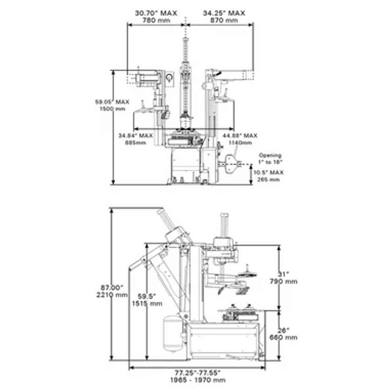
Every piece of equipment designed for vehicle maintenance relies on a set of interconnected systems to carry out specific tasks. These tools are built to perform operations such as installation, removal, and balancing by utilizing various components that interact seamlessly. Understanding the functionality of each section is essential to ensuring smooth and accurate execution during repairs.
The core systems typically include a rotating platform, clamps for securing the wheel, and mechanisms for adjusting and positioning. These features are crucial for controlling the wheel’s placement, enabling precision throughout each task. Additionally, the hydraulic and pneumatic systems contribute to powering the tool, allowing smooth movements and effortless handling of heavy parts.
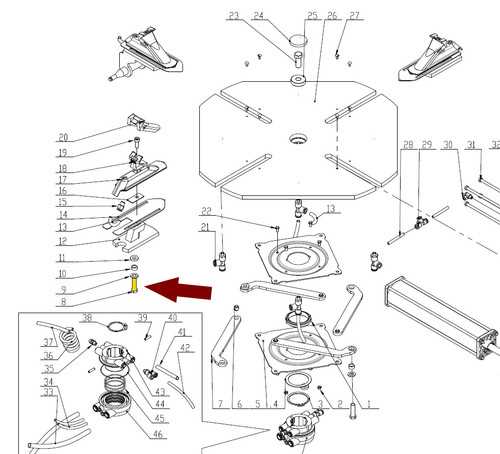
Each of these systems is designed with efficiency in mind. Proper synchronization between the various components ensures that all functions are carried out with minimal effort, leading to faster, more accurate results. Understanding how these mechanisms interact is fundamental for maintaining the equipment and avoiding potential operational issues.
Exploring the Layout of Tire Machine Parts
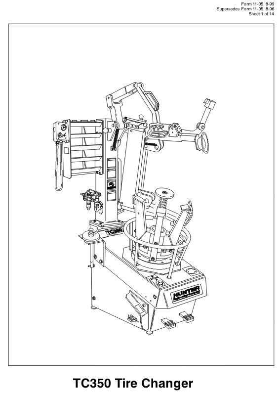
The design of repair equipment involves careful placement of various elements to ensure efficiency and smooth operation. Each section has a designated function, and their positioning plays a key role in achieving optimal performance. Understanding the arrangement of these components is crucial for both troubleshooting and effective use during repairs.
The layout typically includes several key features, such as:
- Rotating platforms for precise wheel positioning
- Clamps to secure the wheel securely during operations
- Adjustable arms to handle various sizes and weights
- Hydraulic systems to control movement with ease
- Pneumatic features for additional support and functionality
Each of these elements is positioned in a way that allows for seamless interaction between systems. The layout ensures that the technician can quickly and efficiently perform tasks without unnecessary delays or errors. Proper understanding of how these components are arranged helps in optimizing workflow and maintaining the equipment’s longevity.