When it comes to maintaining and repairing a trolling motor, understanding the internal structure is essential. Knowing the specific components that make up the system will allow for smoother repairs and better overall performance. In this section, we’ll dive into the various parts that play a crucial role in the motor’s functionality.
Familiarizing yourself with these elements is important not only for maintenance but also for troubleshooting potential issues. From the propeller to the electrical connections, each part has its specific function. By grasping how these parts interact, you can ensure that your motor operates at its full potential.
Whether you’re replacing a faulty part or performing regular maintenance, understanding the breakdown of the system will help guide your decisions. By identifying the key components, you’ll be more prepared to address any challenges that arise.
Motorguide X3 Motor Components

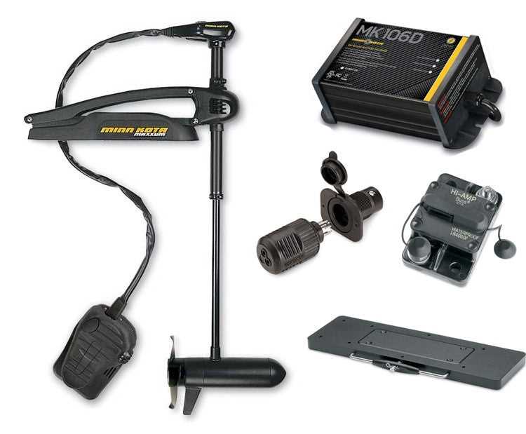
The motor assembly consists of several essential elements that work together to provide efficient propulsion and control. These components are designed to handle various operational demands, ensuring smooth and reliable performance on the water. From the electric motor to the steering system, each part contributes to the overall functionality.
The core of the system is the drive motor, responsible for generating the necessary power to move the boat. It is supported by a series of internal components, including the shaft, bearings, and the propeller. These elements allow for precise control over the speed and direction of the vessel.
Additionally, the control system ensures that the motor can be adjusted to the desired settings. This includes the throttle, speed control, and steering mechanism, which all play crucial roles in maintaining the boat’s trajectory and responsiveness. Proper understanding and maintenance of these components are vital for maximizing the lifespan and efficiency of the motor.
Understanding the X3 Wiring System

The electrical setup of the motor is a crucial aspect of its overall functionality. It ensures that all the components receive the necessary power to operate efficiently. A well-organized wiring system is essential for the smooth performance of the entire unit, as it connects the motor, control panel, and power sources.
Key Components of the Electrical Setup

The wiring network includes several key elements such as the battery connections, control switches, and power leads. Each of these components plays a specific role in distributing electrical power to the motor and auxiliary features. Understanding how they interact can help prevent electrical issues and optimize performance.
Maintaining the Wiring System
Regular inspection and maintenance of the electrical wiring can prevent issues like short circuits or power loss. Ensuring that the connections are secure and free of corrosion is essential for the longevity of the motor. Proper care and attention to the wiring system contribute significantly to the overall reliability and efficiency of the setup.
How to Identify Key Parts
Identifying the essential components of a motor assembly is vital for proper maintenance and troubleshooting. Each element has a specific function that contributes to the overall performance of the system. Knowing how to spot and recognize these key parts can simplify repairs and ensure the system operates smoothly.
Recognizing the Main Components
The first step in identifying critical elements is understanding their primary roles. Below are some key components to look for:
- Motor Shaft: The central component that transfers rotational power to the propeller.
- Control Switches: These components allow users to adjust speed and direction.
- Battery Connections: Ensure power is properly supplied to the motor.
- Propeller: The part responsible for creating thrust and moving the vessel.
Steps for Identifying and Verifying Components
To verify the condition and function of these components, follow these steps:
- Inspect each component visually for wear or damage.
- Check for proper electrical connections and ensure there are no loose wires.
- Test individual parts for functionality using a multimeter or appropriate tools.
- Replace any faulty components immediately to avoid operational issues.
By recognizing and understanding these key elements, you can ensure efficient maintenance and timely troubleshooting for better performance. Regular checks and a solid understanding of each part will make repairs and adjustments more straightforward.