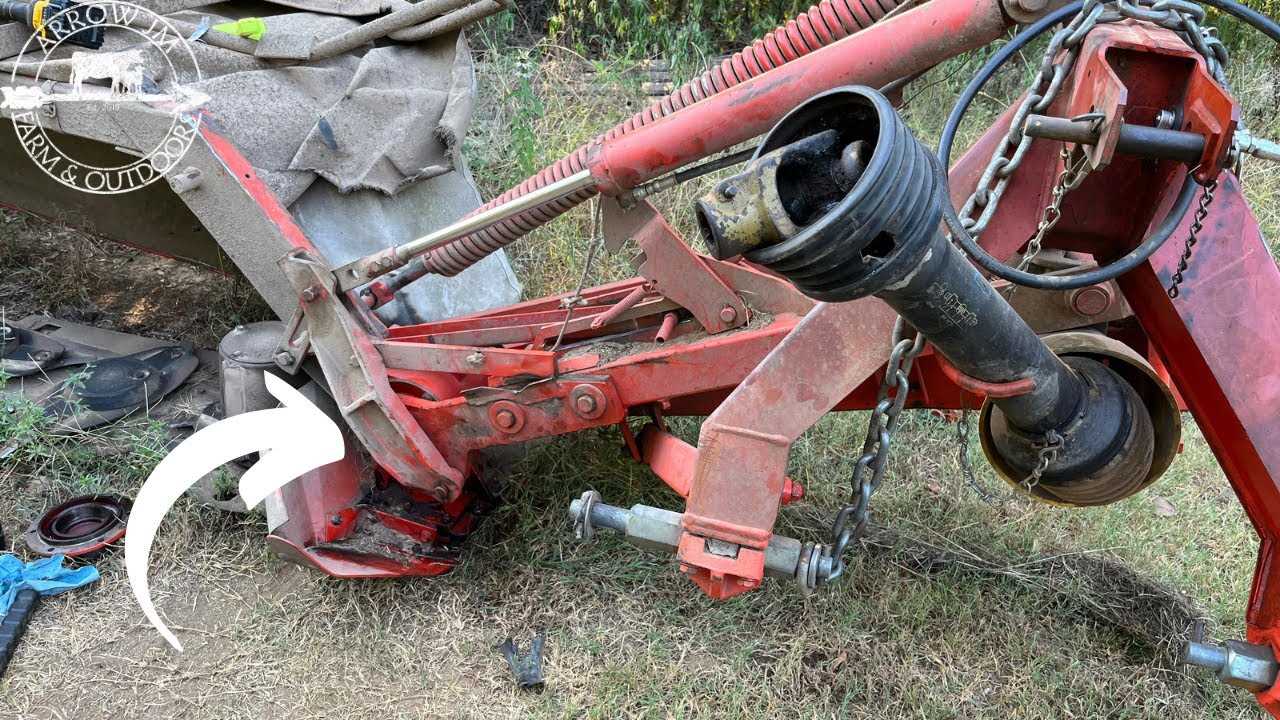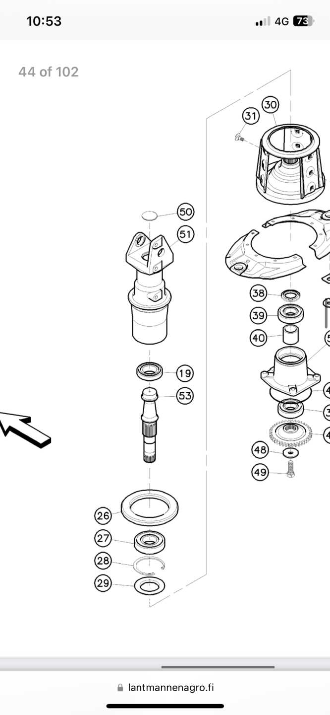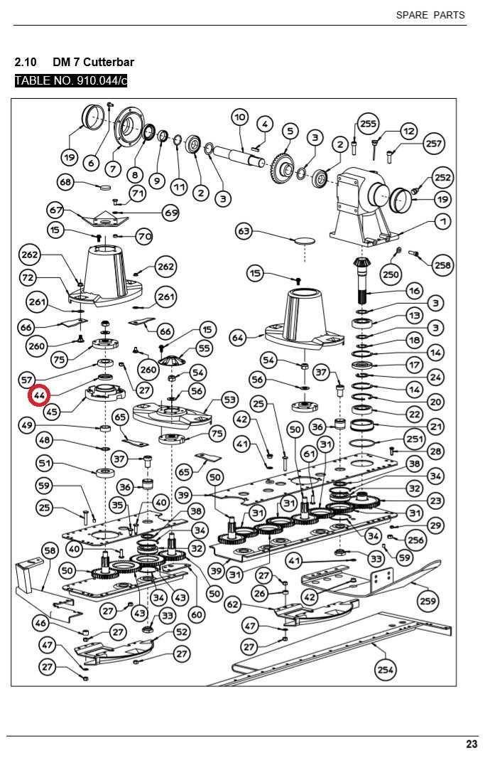
When working with agricultural machinery, it’s essential to have a clear understanding of its various elements and how they function together. Knowing how each component contributes to the overall operation ensures better maintenance and improves machine longevity. This guide will help you familiarize yourself with the different parts of farming machinery used for cutting and harvesting tasks.
Efficient operation depends on the proper alignment and functionality of these elements. By analyzing the configuration of each piece, operators can detect wear and tear early, ensuring smooth performance throughout the season. This article will give you insights into how to interpret technical drawings for agricultural equipment to support effective troubleshooting and repairs.
Whether you’re a seasoned farmer or new to machinery, understanding these crucial components allows you to make informed decisions about maintenance, repairs, and replacements, optimizing your equipment’s productivity. Let’s dive into the details and explore the inner workings of these tools.
Understanding the Kuhn Disc Mower

Efficient farm equipment is vital for successful crop and forage management. The machinery designed for cutting and harvesting plays a crucial role in ensuring the timely and effective completion of tasks. These tools rely on well-coordinated mechanical elements that work together to provide consistent results in various agricultural settings.
Precision and durability are key factors in selecting high-quality farming equipment. For optimal performance, every component must be aligned correctly and maintained regularly. The inner workings of such machines are complex, involving a system of interconnected parts that ensure smooth operation under demanding conditions. Understanding how these components contribute to the overall functionality is essential for operators and technicians alike.
By familiarizing yourself with the system’s configuration and each piece’s role, you can enhance operational efficiency, prevent breakdowns, and extend the machine’s lifespan. A thorough understanding of the equipment’s design also allows for faster troubleshooting and easier repairs when issues arise, ultimately leading to less downtime and better productivity on the farm.
Key Components of the Mower System
To achieve optimal performance and reliability in agricultural tools, it’s important to understand the fundamental elements that make up the cutting mechanism. Each component has a specific role, contributing to the overall efficiency and durability of the equipment. Knowing how these parts interact ensures that the machinery operates smoothly and that any issues can be quickly addressed.
Core Elements of the System
- Cutting Blade Assembly: Responsible for executing the cutting action, these blades must be sharp and robust to handle various field conditions.
- Drive Mechanism: Transfers power from the engine to the cutting system, ensuring consistent movement and performance.
- Frame and Support Structure: Provides stability and support for the entire system, keeping all components in place and ensuring they function correctly.
- Hydraulic System: Controls the height and tilt of the cutting elements, allowing for adjustments based on the terrain.
Importance of Regular Maintenance

- Inspection: Regular checks for wear and damage help identify potential issues before they affect performance.
- Lubrication: Keeping moving parts well-lubricated ensures smooth operation and reduces the risk of breakdowns.
- Replacement: Timely replacement of worn-out components guarantees that the system continues to work efficiently.
Each of these parts plays a crucial role in the machinery’s performance. Understanding their function allows operators to make informed decisions about maintenance, repairs, and upgrades, ultimately enhancing the tool’s efficiency and extending its operational life.
How to Read the Parts Diagram

Interpreting technical illustrations is a valuable skill for anyone working with complex machinery. These visual representations help identify individual components and their relationships, making it easier to understand the inner workings of the system. Properly reading these illustrations ensures that you can troubleshoot, maintain, and repair the equipment with confidence.
Typically, such illustrations include labeled components, numbers, and lines indicating how each part fits together. Familiarity with the symbols and terms used in these diagrams is essential for quick reference during maintenance or repairs. Pay attention to key features like component numbering and the corresponding list of parts, as this will guide you in identifying each element correctly.
Additionally, understanding the orientation and scale of the illustration helps you visualize how the components interact in real-world applications. Being able to accurately read these visual guides makes it easier to replace or repair parts, improving the machine’s overall efficiency and reducing downtime.