Maintaining complex agricultural machinery requires a clear understanding of its individual elements and their functions. A well-organized layout of each component plays a crucial role in ensuring optimal performance and longevity. This section will provide an overview of key machinery parts, their interconnections, and the steps involved in effective maintenance.
By studying the design and layout of various agricultural tools, operators can easily identify issues and perform repairs without the need for constant professional help. Knowing how each piece fits into the overall structure is essential for anyone working with these machines.
Detailed technical illustrations can be invaluable for anyone attempting to troubleshoot or replace components. Whether you are a seasoned technician or a new user, understanding these visual guides simplifies the repair process and helps prevent costly mistakes. The following sections will break down the essential parts and their functions in detail.
Understanding the Krone Mower Parts

Effective operation of agricultural machinery depends heavily on the functionality of its individual components. Each element within the system has a specific role to play in ensuring smooth and efficient performance. Understanding how these components work together is essential for proper maintenance and troubleshooting.
Every tool or machine has its unique structure, composed of moving and stationary parts that work in unison to accomplish a task. Knowing how these elements are arranged and interact will help operators detect any faults quickly and make informed decisions about repairs or replacements.
Core components like the cutting mechanism, drive system, and frame are designed to withstand demanding work conditions. Regular inspection of these parts can prevent costly damage and improve the machine’s overall reliability. By understanding their layout and function, you can extend the lifespan of your equipment and maintain optimal performance throughout its service life.
Key Components of Krone Disc Mower
To ensure the smooth operation of any agricultural tool, it’s crucial to understand the essential elements that make up its design. Each component, from the cutting mechanism to the frame, has a specific function that contributes to the overall performance and efficiency. Familiarity with these core elements allows for better maintenance, troubleshooting, and repairs.
The most vital components of such machinery include the cutting blades, which are responsible for the primary task of trimming and cutting. These parts need to be sharp and durable to handle the constant wear from vegetation. Another key element is the drive system, which powers the entire mechanism, ensuring that the blades rotate at the required speed for effective cutting.
Additionally, the support frame provides structural integrity, withstanding harsh working conditions. It holds all the moving parts in place and ensures that the machine remains balanced during operation. Understanding how these components function together is critical to keeping your equipment running smoothly and efficiently for years to come.
How to Read Krone Mower Diagrams

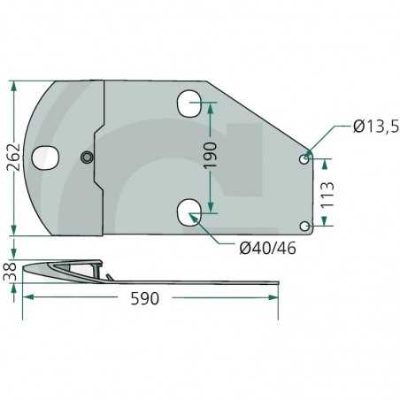
Understanding technical illustrations is crucial when working with complex agricultural equipment. These visual guides provide a detailed overview of the components, their arrangement, and how they function together. Learning to interpret these schematics can simplify repairs, part replacements, and maintenance tasks, making them an invaluable resource for operators and technicians alike.
Identifying Key Symbols and Labels

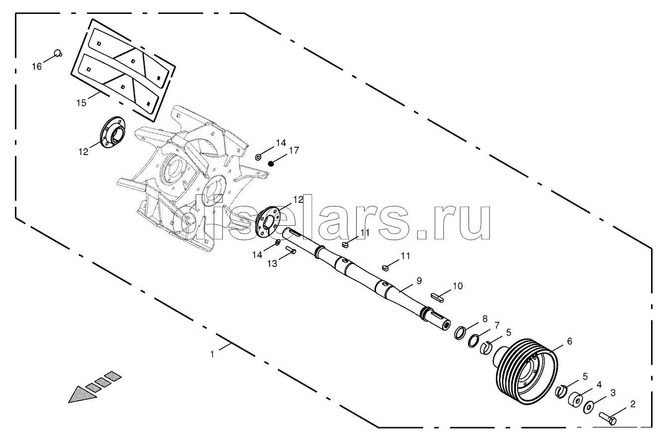
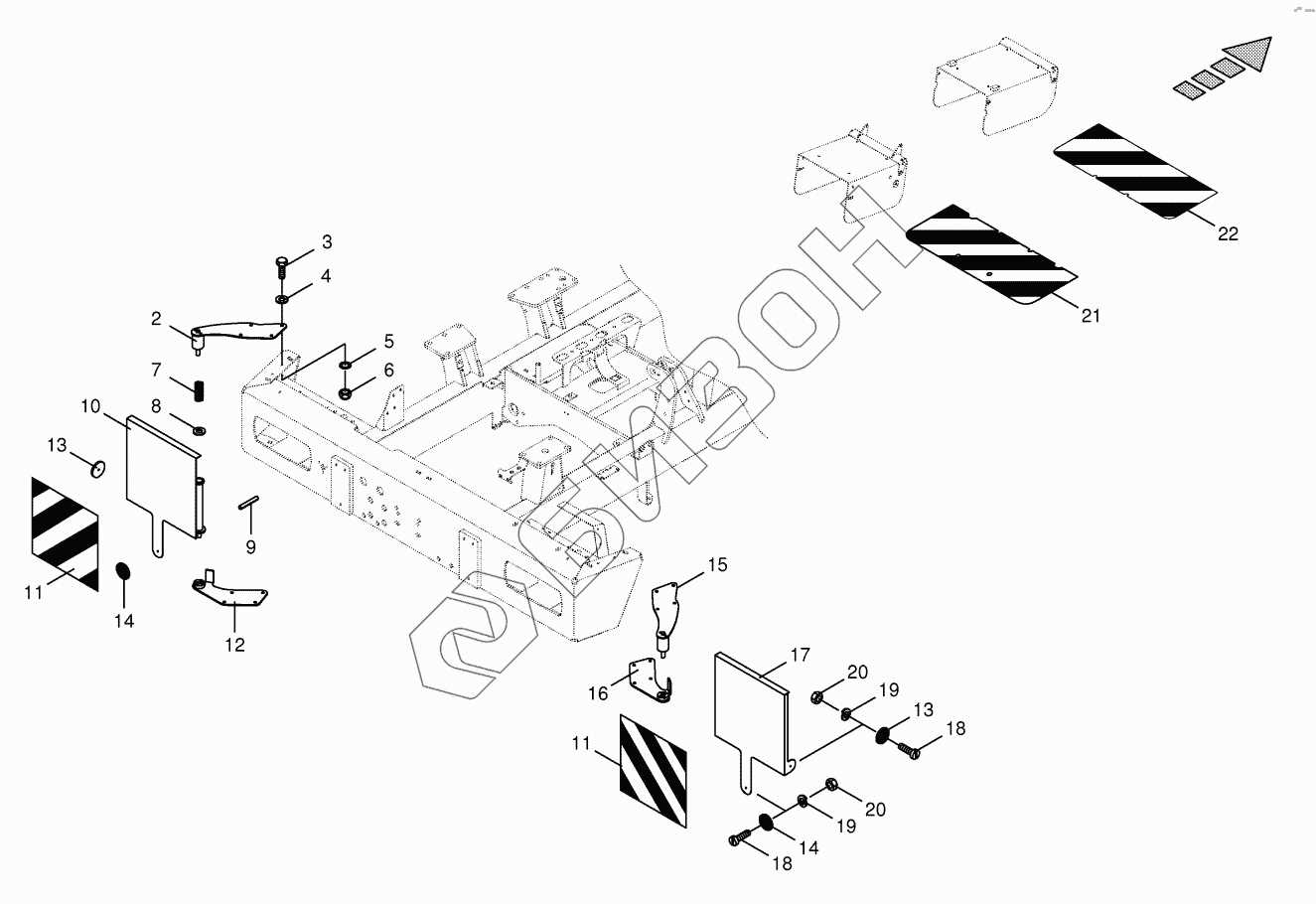
Most technical illustrations use a system of standardized symbols and labels to represent various parts. It’s important to familiarize yourself with these symbols, as they allow you to quickly identify each component and its function. These visual cues often include numbers, lines, and arrows that point to specific elements, helping you understand how parts interact with each other.
Understanding the Layout and Connections
The layout in these illustrations typically shows the equipment from multiple angles, allowing you to see how different parts are connected. Pay close attention to how components are linked, as this can provide insight into the assembly or disassembly process. Analyzing the connections between parts ensures that you can accurately troubleshoot issues and perform efficient repairs.