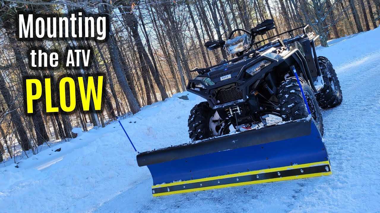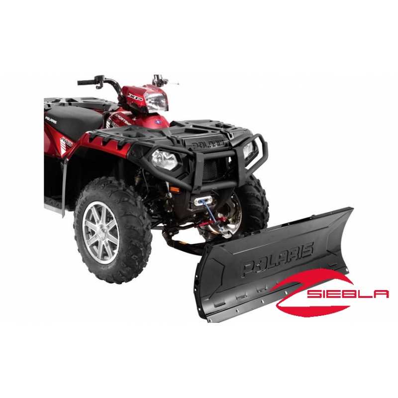
Maintaining snow clearing machinery requires a clear understanding of its key elements. Identifying each component and its role is essential for effective operation and repair. Proper knowledge of these parts allows users to troubleshoot, replace, and maintain their equipment with ease.
Diagrams play a significant role in this process by providing a detailed visual representation of the system. By carefully studying these illustrations, users can locate specific components and understand their interconnections.
Whether you’re a professional or a hobbyist, mastering the inner workings of your snow removal tool ensures longevity and reliable performance. A thorough review of each part can prevent unnecessary repairs and enhance the efficiency of your machine during cold seasons.
Understanding Snow Removal Equipment Components

When working with snow clearing machinery, it is important to comprehend the functionality of each individual component. Understanding how these elements interact with each other ensures the equipment performs optimally and lasts longer. Whether for routine maintenance or troubleshooting, a clear grasp of the system’s key elements makes a significant difference in its operation.
Each tool within the system serves a specific role, from ensuring smooth movement to providing stability and control. Knowing the design and placement of each part allows users to detect wear and tear, enabling timely replacements or adjustments to prevent breakdowns.
By familiarizing yourself with these components, you’ll improve your ability to operate and maintain the machinery efficiently. Recognizing how the pieces fit together enhances your understanding of the system as a whole and ensures that you can take appropriate action when needed.
Key Parts of Snow Removal Equipment
Every snow clearing tool consists of several crucial components that enable smooth and efficient operation. These essential elements are designed to work together, ensuring the machinery can handle challenging conditions. Understanding each part’s function is vital for both new users and those seeking to maintain or repair the equipment.
Some of the most important components include the motor, which drives the mechanism, and the frame that provides the necessary support and stability. The attachment system is another critical aspect, as it allows the device to interface with the surface being cleared effectively.
Additionally, the control system, which includes the steering and operational adjustments, plays a central role in maneuvering the equipment. A clear understanding of these key components helps users operate the machine safely and troubleshoot potential issues when they arise.
How to Read the Parts Diagram
Understanding how to interpret visual representations of a system is essential for effective maintenance and troubleshooting. These detailed illustrations serve as a guide, helping users identify specific components and their relationships within the machine. By following a few simple steps, anyone can learn to read and use these resources to their advantage.
Here are some key tips for reading the visual guide:
- Identify Key Components: Start by locating the main elements of the system. These are often highlighted or labeled for easy identification.
- Follow the Labels: Each part will typically be marked with a unique identifier. These labels help you cross-reference the part with the manual for further details.
- Understand the Layout: Most guides will display the parts in a logical arrangement. Familiarize yourself with the layout to make it easier to trace the flow of the system.
By becoming familiar with the parts diagram, you’ll be able to pinpoint problems, replace damaged components, and ensure smooth operation of your equipment.