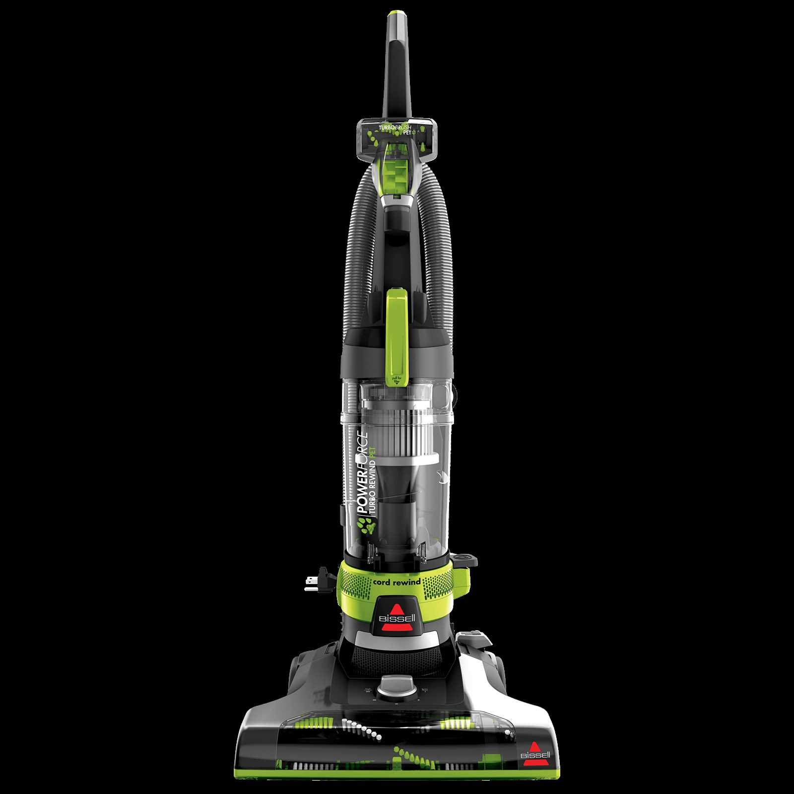
Maintaining a vacuum cleaner requires a clear understanding of its internal structure and the role of each component. A well-organized visual guide can simplify the process of identifying key parts, making it easier to perform repairs or replacements when needed. Whether you’re troubleshooting a specific issue or looking to enhance the performance of your device, knowing the layout of its components is essential.
In this section, we will explore a detailed layout that highlights the various elements of your cleaning appliance. By familiarizing yourself with this guide, you can quickly locate the parts responsible for common malfunctions. Recognizing the function of each part ensures a more efficient approach to repair and maintenance.
Understanding the design will also help in identifying worn-out or broken components. This knowledge not only aids in troubleshooting but also empowers you to make informed decisions when selecting replacement parts. With this guide, you’ll be prepared to keep your vacuum cleaner running smoothly.
Understanding the Bissell Powerforce Helix Layout
When working with an upright vacuum cleaner, it’s essential to grasp how the different components fit together for optimal performance. The internal arrangement of various sections can significantly influence the machine’s efficiency. A well-structured layout ensures that each piece contributes to the overall function, enabling the cleaner to tackle various surfaces and dirt types effectively. Gaining insight into this structure helps users maintain their device better and troubleshoot any potential issues.
The configuration typically includes the motor assembly, filtration system, and brush mechanisms, which interact to deliver powerful suction. Each of these units has a specific role, from capturing debris to enhancing airflow, and understanding how they align with one another can improve troubleshooting efforts. Knowing where each part fits in the design makes it easier to perform repairs or replace faulty components without disrupting the vacuum’s integrity.
Additionally, understanding the internal setup allows for proper maintenance, ensuring longevity and peak functionality. Each piece, when correctly positioned, maximizes the machine’s suction ability, preventing clogging and wear over time. By familiarizing oneself with how the layout is organized, users can make informed decisions about upkeep, ensuring the device operates at full capacity for years.
Common Issues and Parts Replacement Tips
Vacuum cleaners are subject to wear and tear over time, leading to a variety of common issues that can affect performance. Identifying and addressing these problems promptly can save users from more significant repairs. Understanding which components are prone to damage and knowing how to replace them can ensure the device continues to operate efficiently. In this section, we explore frequent malfunctions and offer practical advice on how to address them by replacing worn-out or damaged components.
Loss of Suction Power
One of the most common issues users face is a decrease in suction efficiency. This can be caused by blockages in the hose, clogged filters, or a malfunctioning brush roll. To resolve this, start by inspecting the hose for any debris or obstructions. Clean or replace filters regularly to prevent clogging. If the brush roll is not turning properly, check for tangled hair or debris and clean it thoroughly. In some cases, it may be necessary to replace the brush roll or motor if they show signs of damage or wear.
Unusual Noises or Vibrations
If the vacuum starts making strange noises or vibrating excessively, it could indicate a problem with the motor, belt, or roller. Check the belt for any signs of wear or breakage and replace it if needed. Inspect the motor for any loose parts or damaged bearings. If the issue persists, examine the roller brush for blockages or damage that could cause abnormal movement. Replacing the motor or belt may be necessary to restore smooth operation.
How to Identify Components in the Diagram
Understanding how different sections of an appliance come together is crucial for effective maintenance and repairs. Identifying each individual element in the schematic representation helps you know exactly where to focus when troubleshooting or replacing faulty components. Here, we break down the process of recognizing each part and explain how to use the visual guide to simplify repairs and part replacements.
Start by familiarizing yourself with the overall layout of the machine. The visual representation typically breaks the system down into key sections, each with a distinct function. Follow these steps to ensure accurate identification:
- Locate the motor assembly: This is usually positioned centrally in the diagram, as it powers the entire system. Look for labels like “motor” or “drive unit.”
- Identify the filtration components: These parts are generally found near the intake area, marked with terms like “filter” or “dustbin.” They are essential for maintaining airflow and suction.
- Find the brush roll: The rotating brush mechanism is often located at the bottom of the schematic. Check for terms like “brush roll” or “agitator” to locate this component.
- Check the hose and attachments: Flexible tubing and attachments for cleaning different surfaces are often shown extending from the main body. These parts are essential for versatility and are labeled with words like “hose” or “extension tube.”
Once you’ve located the components, it’s easier to follow the lines connecting each section. These connections often represent the assembly’s operational flow. Understanding the layout will make it clear where potential issues might occur and which parts may need replacement or servicing.