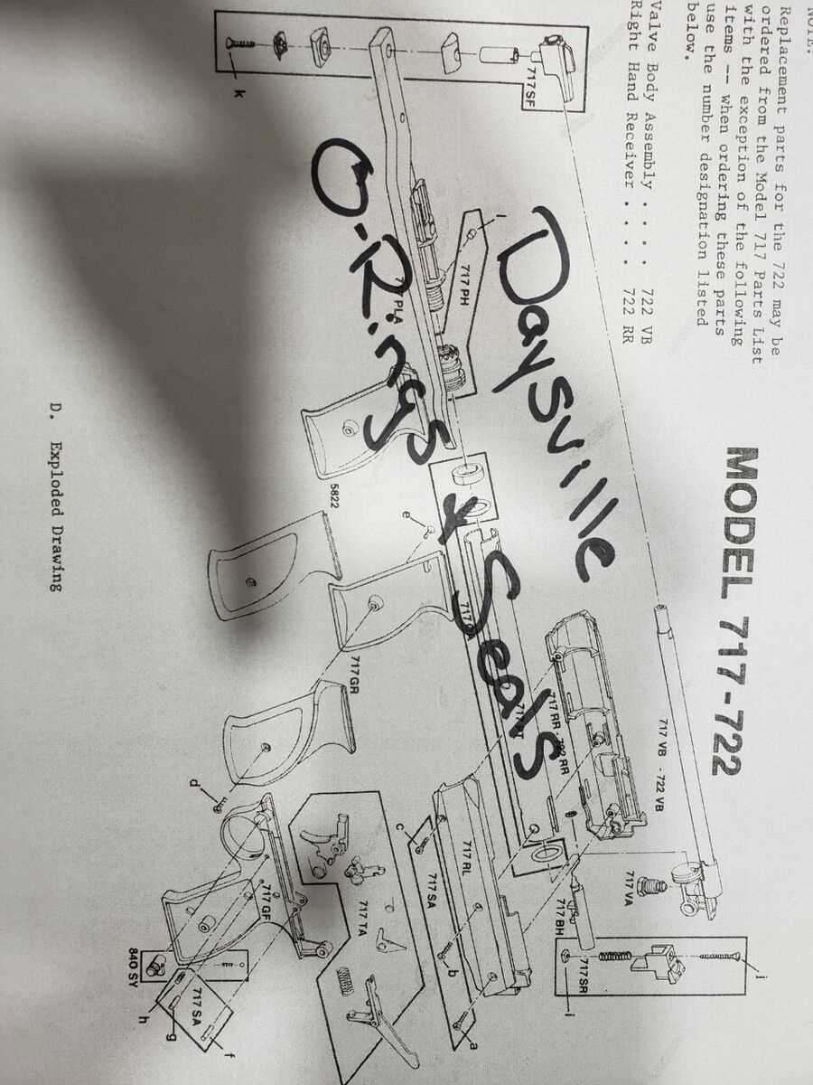
In any mechanical device, knowing the layout and function of each individual element is essential for proper operation and maintenance. A clear visual representation helps in identifying how each part fits together and contributes to the overall performance of the system. Whether you’re troubleshooting or assembling a unit, having an accurate reference guide can save time and prevent errors.
Reading a clear schematic is key to understanding the relationship between different components. It provides a visual map, enabling users to pinpoint specific areas of interest quickly and efficiently. By studying such references, users can better comprehend the device’s structure and ensure proper functionality.
However, even with a helpful guide, challenges may arise. Certain parts may wear out over time, and identifying these weak points becomes crucial for timely repairs. Knowing where issues typically occur allows for faster diagnostics and more effective solutions, ensuring the longevity of the equipment.
Understanding the Components
Each device relies on a set of individual elements, each serving a specific purpose to ensure the smooth operation of the entire system. Understanding how these components interact and their respective roles can provide valuable insights for anyone looking to maintain or troubleshoot the equipment. Whether you are assembling a new unit or diagnosing an existing one, it is crucial to be familiar with the function of each part within the mechanism.
Every component within the structure is designed with a particular function in mind, from power regulation to structural support. Some parts work together in harmony to achieve a single outcome, while others play a supporting role, ensuring stability and durability. By recognizing these functions, users can better understand the flow of energy and information within the system.
For effective maintenance, it’s important to identify the various elements and their connections. Knowing which components are essential for optimal performance can help prioritize repairs and replacements, reducing downtime and extending the lifespan of the equipment. A comprehensive understanding of the device’s internal workings ultimately leads to a more efficient and reliable experience.
How to Read the Schematic
Interpreting a visual guide of a device’s internal structure can seem overwhelming at first, but with the right approach, it becomes a valuable tool for understanding the layout of essential elements. A clear and well-organized reference makes it easier to locate specific sections and identify how the components interact with each other. Mastering this skill is crucial for troubleshooting, assembly, and maintenance.
Identifying Key Symbols
In any schematic, different symbols represent various components within the system. These symbols follow a standardized format, allowing you to easily recognize each part and its function. It’s important to familiarize yourself with these conventions to efficiently navigate the guide. By understanding the meaning behind each symbol, you can quickly identify power sources, connections, and structural elements.
Understanding Component Placement
The layout of the guide is designed to provide a logical flow, with components placed in a manner that reflects their physical arrangement within the system. Parts that work together or are physically close to each other in the real-world setup will usually appear near one another in the schematic. Recognizing this pattern helps users understand the flow of power, data, and structural integrity, making it easier to pinpoint potential issues.
Common Issues with Components
Even the most well-designed systems can encounter problems over time, often due to wear and tear or improper handling. Identifying common issues with the internal elements is essential for troubleshooting and maintaining proper functionality. By being aware of typical problems, users can quickly address them before they lead to more serious damage.
Some of the most frequently encountered issues involve wear, poor connections, or damage to key components. Here are a few common problems you might encounter:
- Loose or disconnected wiring: Over time, wires can loosen or become disconnected, leading to inconsistent performance or complete system failure.
- Component degradation: Certain elements may degrade or wear out due to regular use, affecting the overall performance of the system.
- Electrical shorts: Improper connections or damaged insulation can result in electrical shorts, which may cause malfunction or even permanent damage.
- Overheating: Some components are prone to overheating, especially if airflow is obstructed or the device is used for prolonged periods without proper cooling.
- Incompatible parts: Replacing original parts with incompatible ones can lead to errors, reduced performance, or system instability.
Regular inspection and prompt replacement of damaged parts can prevent these issues from escalating. By maintaining awareness of these common problems, users can extend the lifespan and ensure the reliable operation of the system.