Understanding the intricate details of mechanical systems is essential for efficient repairs and maintenance. A clear visual representation of each element involved can significantly aid in this process. By breaking down complex machinery into its core components, users can easily locate and identify the parts they need for repair or replacement.
In this guide, we will explore how to navigate and interpret technical illustrations, offering insights into how each part functions within the broader system. Whether you’re troubleshooting or performing routine checks, knowing how to read these detailed schematics will help ensure precision and improve the overall efficiency of your work.
Additionally, we will discuss the most common issues that can be identified through such illustrations and how recognizing these signs early can prevent larger problems from arising. With this knowledge, you will be better equipped to tackle repairs with confidence.
Understanding the 13al78bs023 Parts Diagram

To effectively work with complex machinery, it is crucial to have a clear understanding of its internal structure. Visual representations of a system’s components provide a roadmap for identifying each element and understanding how they fit together. These illustrations simplify the process of troubleshooting, repair, and maintenance by clearly marking every part and its corresponding function.
Interpreting Component Layouts
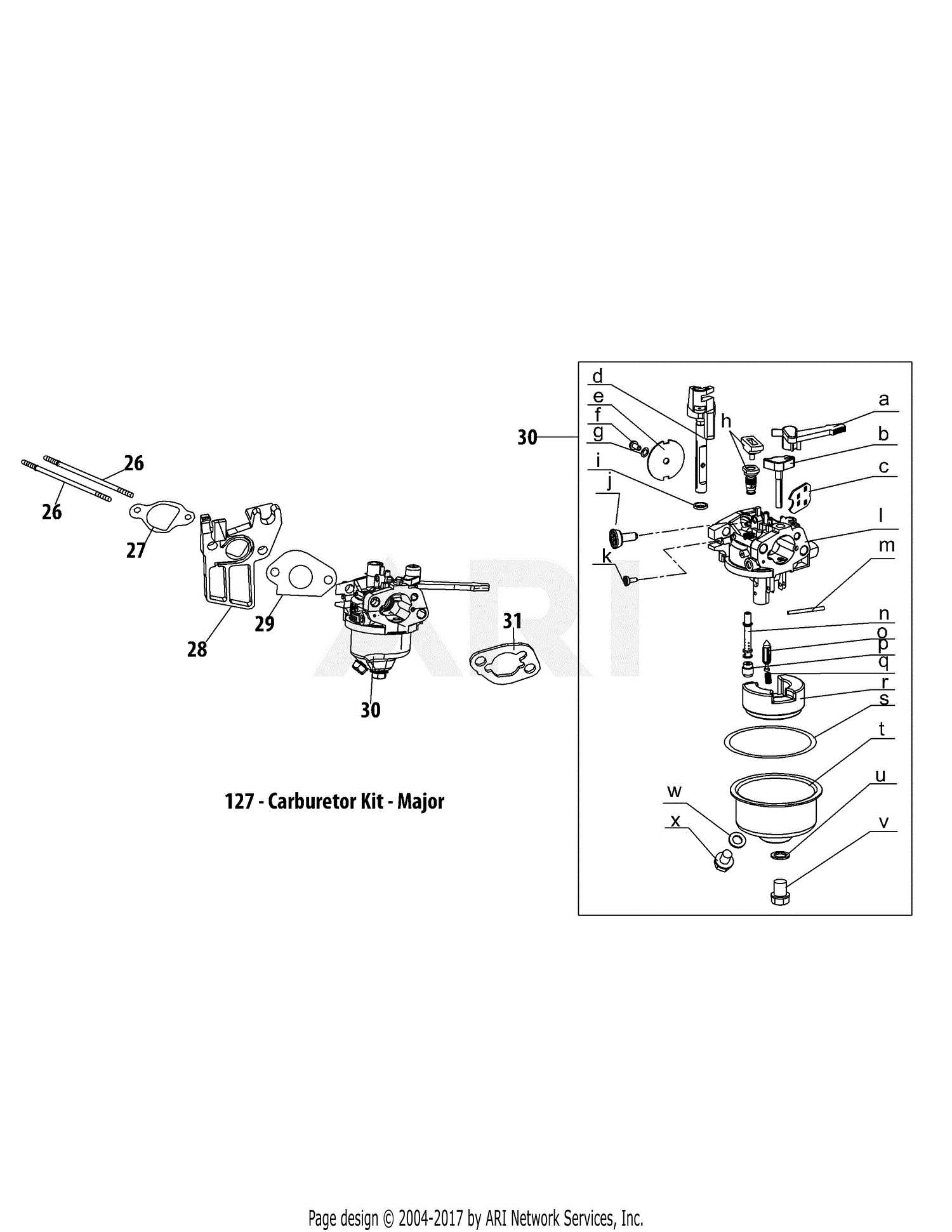
Each schematic offers a detailed view of how individual elements are arranged within the system. Understanding the relationships between these components is key to pinpointing potential issues. A comprehensive layout will often use numbers, labels, and symbols to identify each piece, making it easier to follow and locate them when necessary. Familiarity with these representations can save time during diagnostics and repairs.
Key Features to Look For
When reviewing such technical illustrations, focus on the key symbols and lines that distinguish one part from another. These representations often show critical details such as mounting points, connections, and orientations. Being able to quickly recognize these features helps in not only understanding how everything fits together but also in identifying areas that may require maintenance or inspection.
How to Read the 13al78bs023 Diagram
To successfully navigate technical illustrations, it is important to understand the symbols, labels, and structure that define the layout of each component. The key to interpreting these visuals lies in recognizing the conventions used to depict different elements and how they relate to each other within the system. Mastering this skill will allow you to quickly locate any component and gain a deeper understanding of how the overall system functions.
Begin by focusing on the labels and numbers assigned to each individual piece. These markings typically correspond to a list or reference guide, where further details about the component’s specifications and function are provided. Understanding these references ensures you can match the visual representation with the actual part or system within the machinery.
Additionally, pay close attention to the lines and connections between the parts. These lines often represent functional connections, such as electrical wiring, fluid pathways, or mechanical links. Recognizing the flow of these connections can give you a better idea of how various components interact with one another, helping you identify potential issues or necessary adjustments.
Common Issues Identified in the 13al78bs023 Diagram
When working with mechanical systems, certain recurring problems can often be traced back to specific components or connections. A detailed illustration can be an invaluable tool in spotting these issues before they lead to more serious failures. By recognizing common patterns in the design, technicians can quickly identify potential weak points and address them proactively.
Wear and Tear on Key Components
One of the most common issues highlighted in technical illustrations is the wear and tear on essential elements. Parts that experience constant movement or pressure are often subject to degradation over time. These components may show signs of damage, such as cracks, corrosion, or loose connections. Early detection through a visual representation allows for timely replacement and can prevent breakdowns.
Incorrect Assembly or Alignment
Another frequent problem identified is improper assembly or misalignment of parts. An accurate schematic helps to ensure that each element is in its correct position. Misalignments can lead to inefficiencies or mechanical failures. By reviewing the layout, technicians can confirm that each part is properly aligned and functioning as intended, reducing the risk of malfunction.