When it comes to maintaining your outdoor machinery, having a clear understanding of each individual component is essential. Knowing how to identify, replace, and properly care for the different parts ensures longevity and efficiency in operation. Proper knowledge can prevent unnecessary breakdowns and help you address any issues quickly.
In this guide, we will focus on a specific model’s setup, offering detailed insights into its structure. By exploring the key elements that make up the system, you will be able to visualize how everything works together, giving you confidence when performing maintenance tasks.
Whether you’re a seasoned user or new to the equipment, understanding the various pieces involved is crucial. This section will provide you with all the necessary information to efficiently manage and repair your machine, ensuring its optimal performance throughout the season.
Understanding John Deere Snowblower Components

Every machine designed for snow removal consists of various crucial elements that contribute to its overall functionality. These components work in unison to ensure smooth operation, so understanding each one is key to effective maintenance and repairs. A solid grasp of the main parts will allow users to detect issues quickly and take the necessary steps to restore performance.
One of the most important aspects of machine maintenance is knowing how each part interacts with others. Components like the auger, impeller, and chute all play distinct roles but are interdependent. When one part fails, it can have a domino effect on the entire system, leading to more extensive damage. Understanding their functions and how they connect is essential for troubleshooting and regular upkeep.
In this section, we will break down the main elements of your equipment, highlighting their specific roles and common issues. By becoming familiar with these components, you will be better equipped to address any concerns, keep the machine running smoothly, and extend its service life.
How to Read a Snowblower Parts Diagram

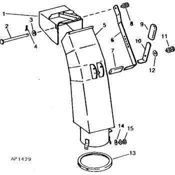
Interpreting an illustration of your equipment’s components is a vital skill for any user. These visual guides provide a clear layout of all the crucial elements, making it easier to identify, troubleshoot, and replace individual parts when necessary. Understanding the symbols, labels, and connections on such a diagram is essential to successfully navigating repairs and maintenance tasks.
The first step in reading these guides is recognizing the basic structure. Each component will be represented by a specific symbol or label, which corresponds to a physical part of the machine. Understanding these references is key to pinpointing where a problem may lie and knowing which replacement part to order.
In addition to identifying individual components, you’ll also need to be familiar with the numbering system or part codes that are often included. These numbers are used to cross-reference with a parts catalog, allowing you to find the exact match when replacing or ordering new parts. By mastering these visual cues and referencing systems, you’ll be able to confidently manage repairs and ensure your equipment runs smoothly.
Maintaining Your John Deere Snowblower

Regular upkeep is crucial to ensure that your machine operates at peak performance throughout the winter season. Proper maintenance not only prevents breakdowns but also extends the life of your equipment. By performing routine checks and making small adjustments, you can avoid costly repairs and keep your system running efficiently.
The most essential aspect of maintenance is ensuring that all moving parts are properly lubricated. This reduces friction and wear, preventing unnecessary damage. Additionally, keeping the intake and discharge areas free of debris ensures that the machine works at its full capacity without clogging or overheating.
Another key step is inspecting the belts, cables, and fasteners for signs of wear or loosening. Tightening or replacing these components before they fail will save time and trouble during heavy use. By familiarizing yourself with the maintenance schedule for each element, you’ll be prepared to perform quick adjustments and keep your equipment in top condition.