Maintaining outdoor machinery requires a solid understanding of its structure and individual elements. By familiarizing yourself with the layout and parts of the system, you can ensure efficient operation and perform necessary repairs. A well-organized setup allows users to easily identify key sections that may need attention over time.
Whether it’s for routine maintenance or addressing specific malfunctions, recognizing how each component fits into the larger system is crucial. Identifying parts quickly saves time and ensures the equipment runs smoothly throughout the season. This guide helps break down the essential elements of your machine, focusing on how each part functions and how to manage them effectively.
Taking the time to understand the design of your machinery makes troubleshooting easier, enabling you to maintain peak performance. Knowing where each element is located and its role will simplify any repairs or adjustments, extending the longevity of the equipment.
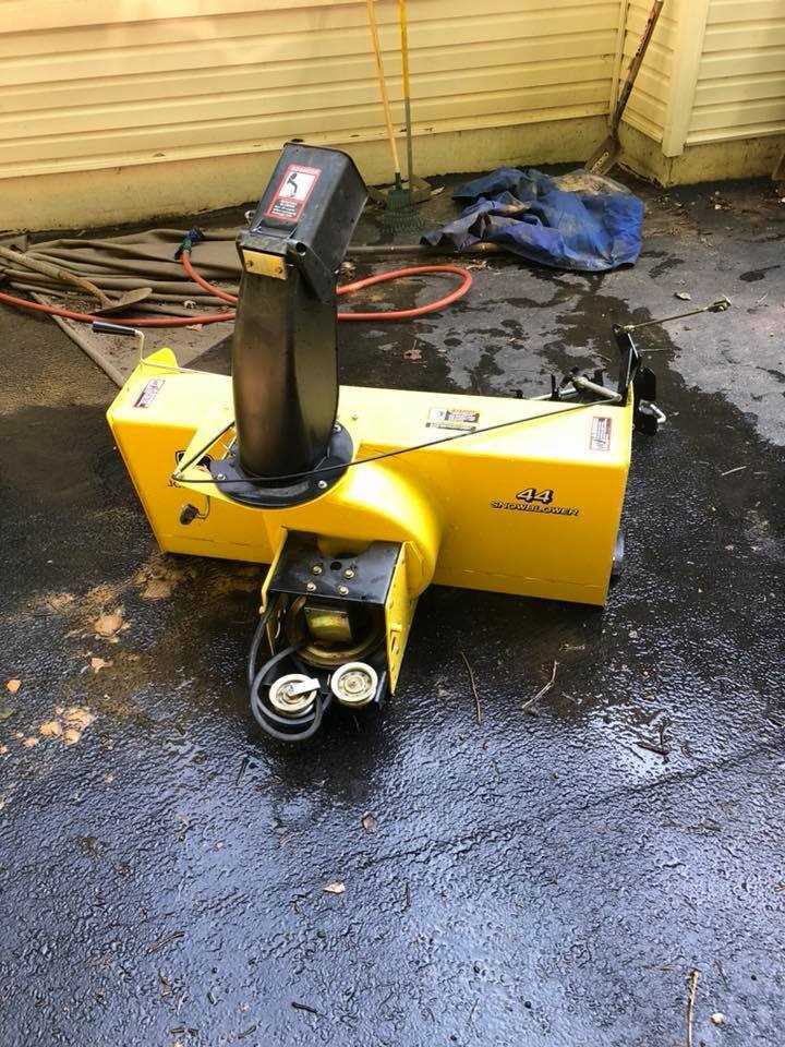
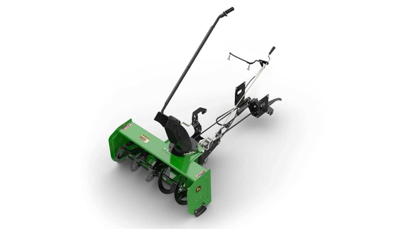
Understanding the 44in John Deere Snowblower

To efficiently clear pathways during winter, it’s essential to understand how the machine operates and what makes it effective. A well-designed system allows for easy maneuvering, powerful performance, and quick results. By examining the main components, users can enhance their ability to maintain and troubleshoot any issues that arise during use.
The machinery is designed to handle various conditions, from light snow to heavier accumulations. Its robust structure and efficient operation rely on well-integrated parts that work in harmony. Understanding each component’s function ensures that users can quickly diagnose any issues and address them appropriately.
- Chassis: The main framework that supports the machine, ensuring durability and stability during use.
- Drive Mechanism: Responsible for powering the system, enabling movement and the rotation of essential elements.
- Auger Assembly: Vital for breaking through the snow and directing it into the chute.
- Discharge Chute: Directs the expelled snow, allowing for precision and control over where it is deposited.
Each of these components plays a crucial role in the overall efficiency of the system. Understanding their interaction helps ensure smooth operation, reducing the likelihood of unexpected breakdowns. Additionally, recognizing signs of wear and tear on individual parts can prevent long-term damage and improve the machine’s lifespan.
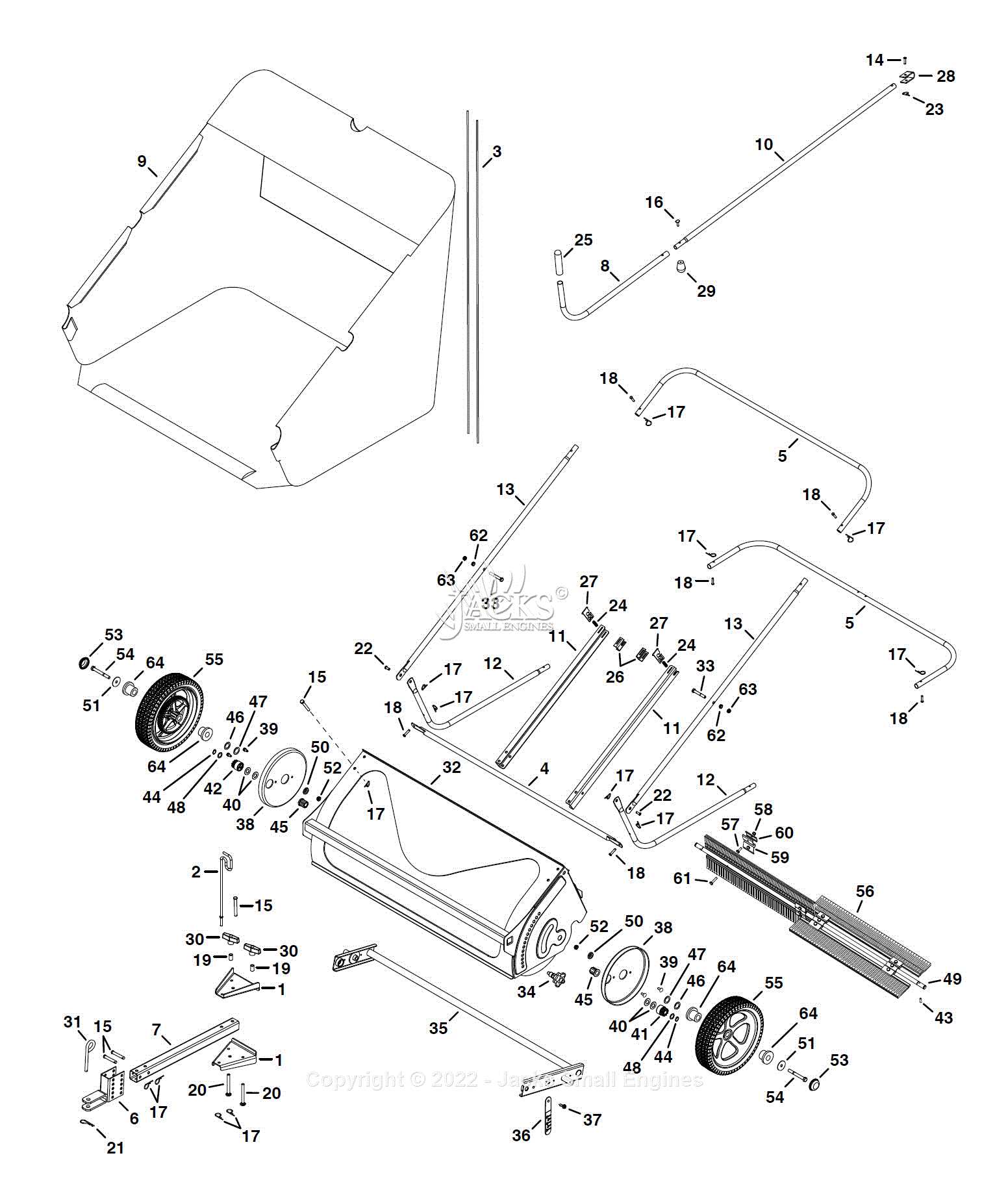
Key Components of the Snowblower Diagram
Understanding the essential components of a machine is critical for its optimal performance and maintenance. Each element plays a vital role in ensuring the equipment works as intended, from initiating movement to handling debris. These fundamental sections are interconnected, and knowledge of their layout helps when performing repairs or upgrades.
The key components of this system include the power source, mechanisms for movement, and tools responsible for clearing and expelling the snow. Familiarizing yourself with these components will not only assist with maintenance but also aid in troubleshooting any issues that may arise during operation.
- Engine Assembly: Provides the necessary power to drive the system and operate the key functions.
- Auger Mechanism: Responsible for breaking up snow and feeding it into the discharge system.
- Drive Belt: Transfers energy from the engine to the moving parts, enabling movement and rotation.
- Chute System: Directs the ejected snow to a designated location, ensuring accuracy and control during clearing.
By identifying each of these components and their connections, users can better understand how the machine operates and how to manage its upkeep. This knowledge is crucial for prolonging the machine’s life and maintaining its performance throughout the colder months.
How to Identify Snowblower Parts for Repair

Properly identifying components for repair is crucial to efficiently address issues that may arise during use. Knowing where to look and which parts need attention allows for faster troubleshooting and more effective repairs. By understanding the system’s design, you can pinpoint malfunctions quickly and take the necessary steps to restore optimal performance.
Inspecting the Machine for Signs of Wear
When dealing with issues, start by visually inspecting the equipment for obvious signs of damage or wear. Look for parts that may appear loose, cracked, or excessively worn. For example, components like the auger assembly or drive belt may show visible signs of strain after extended use. Regular inspections help identify potential problems before they lead to more significant malfunctions.
Referencing the System’s Manual
Having a reference guide or manual is essential when identifying parts for repairs. Manuals often include detailed illustrations and descriptions, making it easier to locate specific components. Understanding the layout and function of each part will help you recognize which ones require attention and determine the proper steps for repair or replacement.