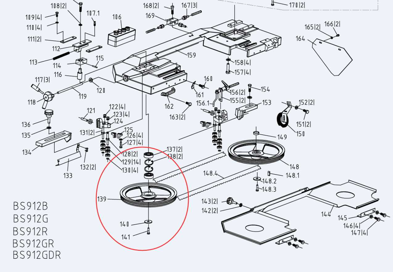
Every woodworking tool consists of a variety of interconnected elements that ensure its proper functioning. Understanding the structure of your equipment is crucial for effective operation and maintenance. Knowing how each component works together can significantly improve your performance and safety during use.
By familiarizing yourself with the key parts, you can easily troubleshoot issues and identify when something needs adjustment or repair. Proper knowledge of your machine not only enhances its lifespan but also empowers you to make informed decisions during usage and maintenance.
In this guide, we will break down the essential elements of your machine, helping you recognize their roles and how they contribute to the overall functionality. Whether you’re a beginner or an experienced user, a clear understanding of these components is invaluable.
Key Components of a Bandsaw
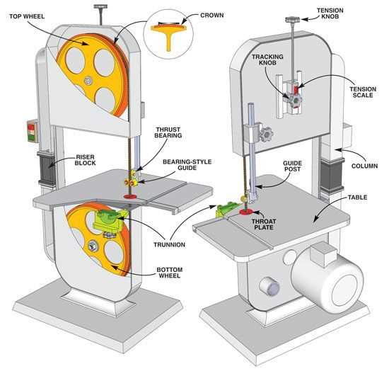
To understand the functionality of a cutting machine, it’s essential to recognize its main structural elements. Each component plays a vital role in ensuring smooth operation and precision. Knowing how these pieces work together allows for more efficient use, proper maintenance, and quick troubleshooting.
Drive Mechanism
The drive mechanism is the heart of the tool, providing the motion needed to power the blade. Typically powered by a motor, this system controls the speed and force with which the blade moves. A well-maintained drive mechanism ensures consistent cutting and prolongs the lifespan of the machine.
Cutting Blade and Tensioning System
The cutting blade is one of the most critical components. It performs the actual cutting, and its sharpness, material, and tension determine the quality and precision of the cut. The tensioning system maintains proper blade alignment and tightness, preventing slips and reducing wear during operation.
How to Read a Bandsaw Parts Diagram
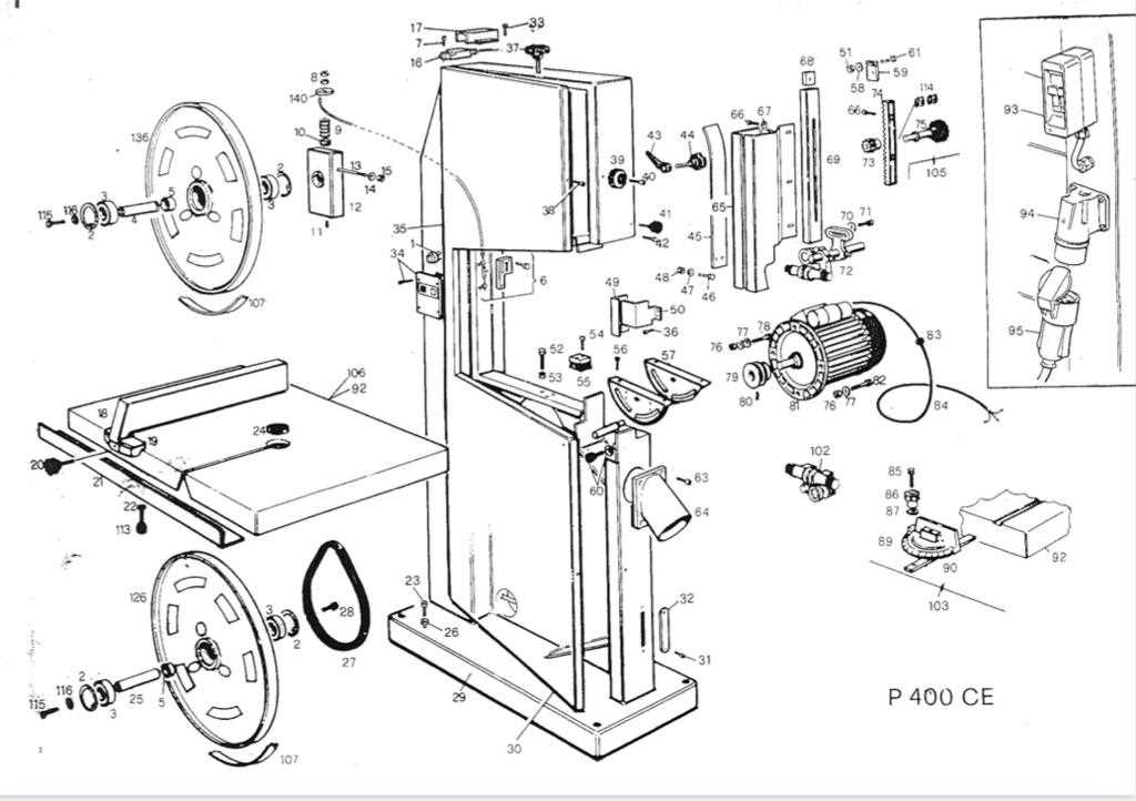
Understanding technical drawings and schematics is an essential skill when working with complex equipment. These visual representations highlight the location and function of each element, making it easier to locate components for repair or maintenance. Learning how to interpret these visuals will help you identify parts and their relationships to each other.
Identifying Key Elements
Each component in a technical drawing is represented by a distinct symbol or label, making it easier to trace their connections. Familiarizing yourself with the standard symbols used in these schematics is the first step in accurately understanding the layout. Components such as the motor, tensioning system, and cutting mechanism will be clearly marked for quick identification.
Interpreting Relationships Between Parts
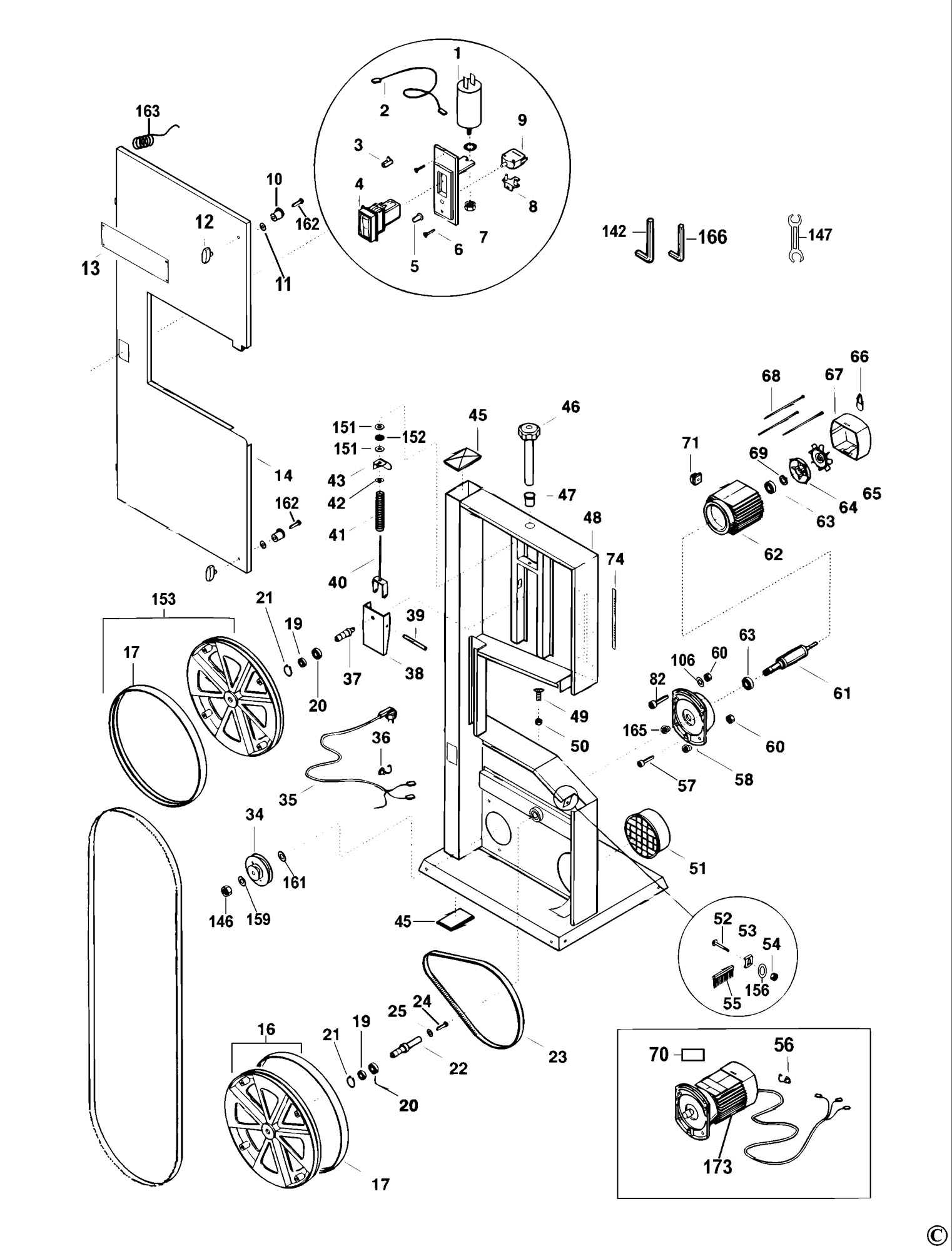
A proper schematic will not only identify individual components but also show how they interact with each other. Arrows, lines, and labels often illustrate the flow of energy or material between parts. Understanding these relationships helps you grasp the overall functionality and workflow of the equipment.
Common Issues with Bandsaw Parts
Like any complex tool, machinery components can wear out or malfunction over time, affecting the overall performance. Recognizing these issues early can save you time and money by preventing further damage. Many of the most common problems arise from misalignment, wear and tear, or insufficient maintenance.
One frequent issue involves the tensioning system, which may lose its effectiveness, leading to blade slippage or poor cut quality. Another common problem is motor failure, often caused by electrical faults or overheating. Additionally, improper blade tracking can cause the blade to move off-center, resulting in inaccurate cuts and unnecessary strain on other parts.