Understanding the intricate elements of a mechanical setup is essential for both maintenance and repair. Each individual piece plays a crucial role in ensuring smooth performance and longevity. By having a clear understanding of how these components interconnect, you can optimize functionality and address any issues that arise.
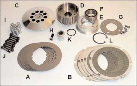
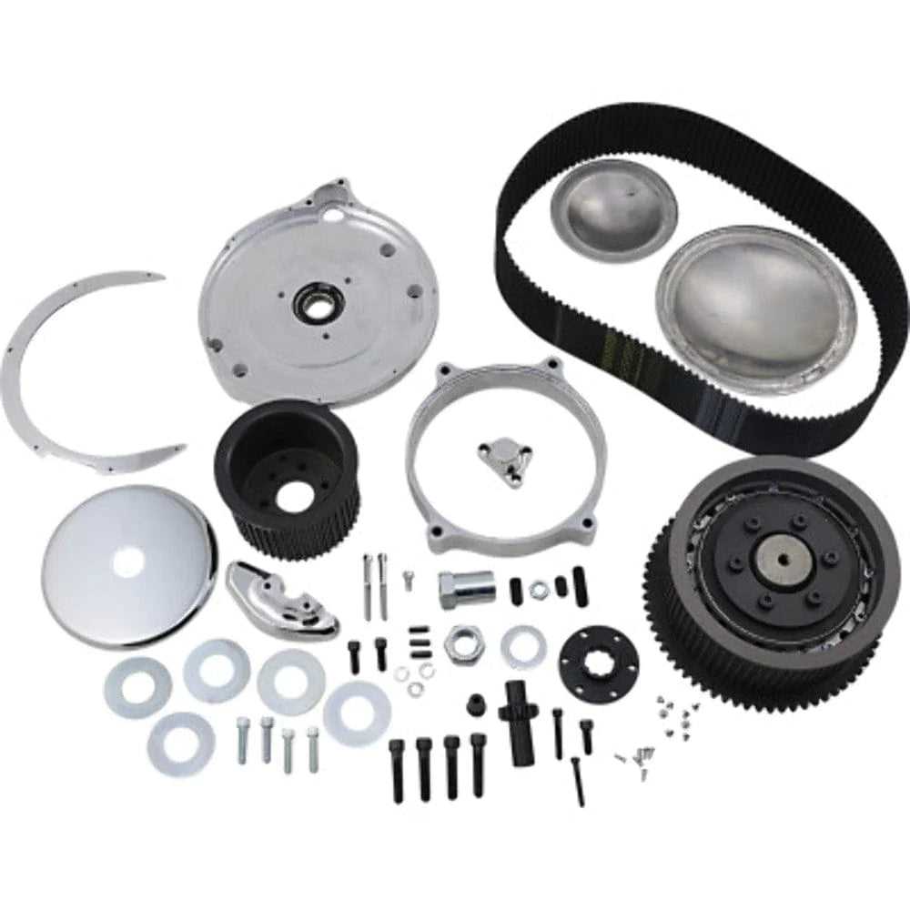
In this guide, we break down the structure of the system, offering a visual representation to help you recognize the role of each element. Whether you’re looking to troubleshoot or enhance your setup, knowing the details of every part makes the process easier and more efficient.
Mastering the assembly of such a system requires familiarity with both its design and how each component functions. This knowledge empowers you to tackle any adjustments or replacements with confidence, ensuring long-term reliability.
Understanding the BDL Belt Drive System

Mechanical systems that rely on rotational power often incorporate various interlinked elements that ensure smooth and efficient operation. The configuration of these components is carefully designed to transfer energy from one part to another while maintaining stability and performance. Properly understanding how these individual components function together is crucial for anyone maintaining or troubleshooting the system.
At the heart of this setup lies a sophisticated network of interconnected parts, each performing a distinct role. These elements work together in harmony to provide the necessary power and control, whether for performance enhancement or everyday usage. Recognizing the importance of each component and how they interact is vital for anyone involved in repairs or adjustments.
Effective functioning is not solely about the individual pieces, but also how they complement one another within the system. Understanding their relationships allows for better decision-making when it comes to maintenance and repair tasks, ensuring optimal performance over time.
Key Components of the BDL Belt Drive

Every mechanical system consists of critical elements that each contribute to the overall performance. In systems that transfer power from one component to another, it is essential that each part is carefully chosen and designed for maximum efficiency. Understanding these key elements helps in both operating and maintaining the setup effectively.
Main Components and Their Functions
One of the core pieces is the central mechanism that connects the various moving elements, allowing for smooth and controlled movement. This component is responsible for ensuring that energy is transferred seamlessly between different parts of the system, enabling consistent power delivery.
Supporting Elements for Stability
In addition to the central mechanism, there are other supportive components that contribute to the overall stability of the system. These parts help maintain proper alignment, reduce friction, and ensure that everything stays in place during operation. Without these elements, the system would be prone to wear and breakdowns.
Each component plays a unique role in sustaining the functionality of the entire system. By understanding their individual contributions, you can better maintain, troubleshoot, and repair the system as needed, ensuring it performs reliably over time.
How to Use the Parts Diagram for Maintenance
Proper maintenance of a mechanical system requires a clear understanding of its structure and components. Having a detailed visual representation of the system allows you to identify each element and its function, making it easier to spot issues and plan repairs. Knowing how to read and use this representation is key to effective upkeep and troubleshooting.
To begin, carefully examine the image, focusing on the arrangement of each part. Pay attention to how they connect and interact with one another. This insight will help you pinpoint potential problem areas, such as misalignments or worn-out components, which could cause inefficiencies or failure.
During maintenance tasks, use the visual guide to confirm the correct placement and condition of each element. For example, if you’re replacing a specific part, the diagram can ensure that the new component fits properly within the system. Additionally, it provides clarity on how to disassemble and reassemble the setup without damaging any of its parts.
By regularly consulting the visual representation, you can prevent minor issues from escalating into more significant problems, ultimately extending the lifespan and efficiency of the system.