When it comes to maintaining and repairing your vacuum, having a clear visual guide can make all the difference. Understanding the layout and function of each component helps ensure effective troubleshooting and repair. This guide aims to provide the essential information you need to keep your cleaning equipment in optimal working condition.
By exploring how each piece fits together, you’ll gain confidence in handling repairs yourself, saving both time and money. A well-organized reference of the individual sections of the device will allow you to spot any issues quickly and replace any malfunctioning elements efficiently. Whether you’re performing regular maintenance or addressing a specific problem, understanding the layout is key to getting the job done right.
Understanding Vacuum Cleaner Layout

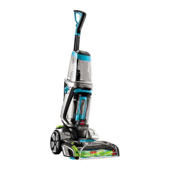
Every vacuum cleaner consists of several essential components that work together to ensure smooth operation. Familiarizing yourself with the arrangement and function of these individual parts is crucial for troubleshooting and proper maintenance. Recognizing how each section contributes to the overall performance of the device will help you identify and address any issues more effectively.
The layout includes various mechanisms such as the suction system, brushes, filters, and motors, each playing a specific role in the cleaning process. By understanding their placement and connection, you can gain insight into how the machine operates and how to perform minor repairs or adjustments. This knowledge makes it easier to maintain the equipment over time and extend its lifespan.
How to Identify Key Components

Recognizing the important elements of your vacuum cleaner is essential for both repairs and routine maintenance. Each section of the device plays a unique role in its overall performance, and identifying them will allow you to diagnose issues more efficiently. The key to effective troubleshooting is knowing where each critical component is located and how it functions within the system.
Start by familiarizing yourself with the central elements like the motor, filter, brush assembly, and suction pathway. Understanding their purpose and interconnection helps pinpoint potential problems. With the right visual reference, you can easily trace the flow of air, check for blockages, and determine if any part is worn or damaged, ensuring the cleaner works as efficiently as possible.
Step-by-Step Repair with Visual Guide

Repairing your cleaning device can be a straightforward process when you follow a systematic approach. Having a visual reference that outlines each component’s location and function simplifies the task and ensures accuracy. This step-by-step method helps you tackle each issue one by one, reducing the risk of missing key details.
Begin by identifying the problem area and referencing the visual guide to pinpoint the faulty part. Once you have located the issue, carefully remove or replace the affected component. Pay attention to the connections and assembly to avoid damaging surrounding parts. After reassembling, perform a quick test to verify the repair, ensuring the cleaner operates smoothly and efficiently again.