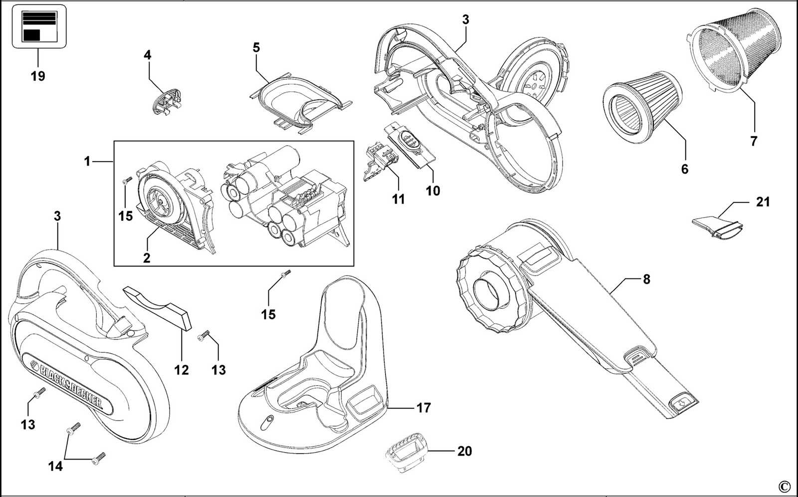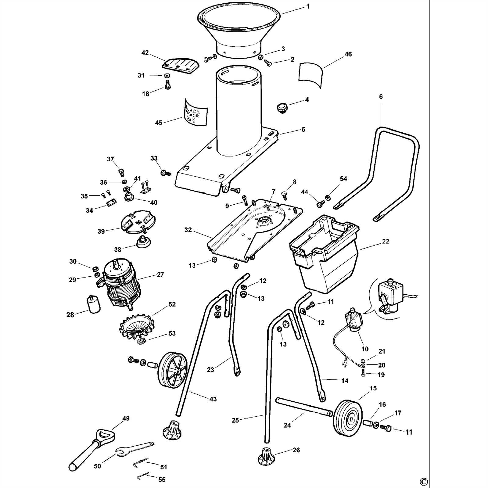
Every mechanical device relies on a precise arrangement of individual elements that work together to perform its intended function. Whether it’s a garden tool or a household appliance, knowing the layout of these components is crucial for effective maintenance and repair. A clear map of each part helps users identify which elements need attention, ensuring a smoother repair process.
In this section, we’ll explore how to approach the layout of essential tool components. We’ll break down the various segments that make up the tool’s internal structure, providing a roadmap for anyone looking to fix or upgrade their equipment. This guide will help you navigate through common issues by showing you which parts are critical for proper operation.
Being familiar with the internal organization of your tool can significantly reduce troubleshooting time. By understanding how the components interact, you can pinpoint problems more accurately and avoid unnecessary disassembly. This knowledge is an essential step in prolonging the life of your equipment.
Understanding the LST140 Component Layout
To effectively maintain or repair your tool, it’s important to understand how its various elements are organized. Each individual component plays a role in the overall functionality, and knowing their placement can make the process of troubleshooting much easier. A well-organized layout helps users identify parts that may require attention or replacement, ensuring a more efficient repair or maintenance process.
In this section, we will focus on key sections and their corresponding components. Understanding the layout is the first step to identifying potential issues and performing accurate repairs. The following list outlines the core groups of components that work together to power the tool:
- Power Supply: Provides the necessary energy for operation.
- Motor Housing: Encases the motor and facilitates movement.
- Control Mechanism: Manages power flow and user inputs.
- Cutting Mechanism: Includes blades or other tools responsible for cutting or trimming.
- Safety Features: Built-in elements designed to protect users from harm.
By breaking down the tool into these groups, users can approach repairs more systematically. Each part affects the tool’s performance, so it is essential to understand their relationships within the overall layout. A solid grasp of this organization not only aids in repairs but also contributes to better long-term maintenance and care of the equipment.
Identifying Key Parts for Repair
When a tool begins to malfunction, identifying the exact components that need repair or replacement is crucial. Without a clear understanding of the key elements, it can be challenging to efficiently troubleshoot and resolve issues. Focusing on the primary components that directly influence the tool’s performance helps narrow down the search and speeds up the repair process.
Common Problem Areas
Several components are more likely to experience wear and tear, making them common culprits when the tool isn’t functioning properly. These areas should be inspected first:
- Power Supply: Issues such as weak performance or failure to turn on often stem from the power supply, including the battery or wiring.
- Motor: A malfunctioning motor may lead to uneven operation or total failure to start.
- Control Switch: The mechanism used to adjust settings can wear down, causing difficulty in turning the tool on or off.
- Cutting Mechanism: Dull or damaged blades can significantly reduce the effectiveness of the tool.
How to Diagnose and Replace
To identify which components need attention, a methodical inspection process is required. First, check the external connections for any visible damage, such as frayed wires or loose parts. Next, test the power supply by ensuring that the battery is fully charged and that there are no issues with the power circuit. Finally, inspect the motor and cutting mechanism for signs of wear or damage, as these are the most likely areas to need repair or replacement.
How to Use the LST140 Diagram

Understanding how to read and utilize a visual map of a tool’s internal structure can make repairs more efficient. These illustrations provide a detailed overview of each component and its position within the overall design, offering a clearer perspective on how to identify, troubleshoot, and replace faulty parts. By following a step-by-step approach, users can easily pinpoint the area that needs attention and proceed with the necessary maintenance or fixes.
When working with such a visual guide, begin by familiarizing yourself with the general layout. The key is to understand the relationship between different components. Start by locating the main functional groups, such as the power source, motor, and control systems. Once these are identified, move on to specific sections that might need repair or replacement. Pay close attention to numbered labels or markers that can indicate which components correspond to specific parts in the tool.
By using this approach, anyone can confidently navigate through the tool’s structure, ensuring that each part is correctly addressed during repairs. With a solid understanding of the layout and how the components work together, the process of fixing or upgrading becomes significantly easier.
Step-by-Step Repair Process
To effectively restore a malfunctioning tool, following a methodical approach is essential. A structured repair process not only ensures that the problem is identified accurately but also prevents unnecessary damage during disassembly and reassembly. By breaking down the process into manageable steps, users can approach the repair with confidence, minimizing mistakes and saving time.
Prepare for the Repair
Before starting, gather all necessary tools and replacement components. Ensure the work area is clean and well-lit to avoid any loss of small parts. Begin by disconnecting any power sources and securing the tool in a stable position to prevent movement while working on it. Carefully review the layout to pinpoint the area that requires attention.
Disassemble and Replace Components

Once you’ve identified the faulty section, proceed with removing the necessary parts. Use appropriate tools to carefully disassemble any fasteners or connections, taking note of the order and placement for easy reassembly. Replace damaged or worn-out components with new ones, making sure each part is securely installed and properly aligned.
After replacing the required parts, reassemble the tool by reversing the disassembly steps. Test the tool to ensure it is functioning properly before fully reassembling it. This step ensures that the repair has been successful, allowing for adjustments if necessary.
Common Issues and Parts Breakdown
Many tools encounter similar problems over time, which often stem from specific components that wear out or malfunction. Understanding these issues and recognizing the affected parts is the key to effective troubleshooting. A breakdown of the common problems and the parts involved allows users to focus on the right areas, ensuring faster repairs and better performance in the long run.
Power Supply Failures
One of the most frequent issues is a failure in the power supply, which can manifest as the tool not turning on or losing power during use. Common causes include worn-out batteries, loose connections, or damaged circuits. Replacing the battery or inspecting the electrical connections can often resolve these problems.
Motor Malfunctions
If the tool is running unevenly or not working at full capacity, the motor might be the culprit. Over time, motors can experience wear due to overuse or lack of maintenance. It’s important to inspect the motor for signs of damage, such as overheating or strange noises. In some cases, cleaning or lubricating the motor can restore its function, but a replacement might be necessary for more severe damage.