Every machine consists of multiple components that work together to provide optimal functionality. Understanding how each part interacts can significantly improve your maintenance and repair skills. This guide focuses on breaking down the essential features of a smaller, versatile device used for various tasks.
Knowing how to identify, replace, and troubleshoot the elements of the tool can save time and prevent unnecessary damage. A clear visual representation of these components will allow you to manage repairs with greater confidence. By learning about the inner workings of this tool, you will be prepared to tackle any issues that arise efficiently.
Understanding the Compact Tool
When working with smaller machines, it’s important to understand the core structure that drives its functionality. These devices are designed to perform a wide range of tasks, and each element plays a key role in ensuring smooth operation. By getting familiar with their basic setup, you can easily handle regular maintenance and troubleshoot any issues that arise.
Key Features of the Device
At the heart of this equipment is a system that stores and releases energy, making it effective for various tasks. The primary components of this machine include mechanisms that help in energy storage, regulation, and efficient output. Each part works together seamlessly to provide consistent performance across a range of applications.
How to Maintain and Troubleshoot

Proper maintenance of this type of equipment involves knowing how to inspect, replace, and adjust its key mechanisms. Regular checks can prevent breakdowns, and understanding how each component functions ensures you’ll be able to address minor issues before they become major problems. With some basic knowledge, you can extend the lifespan of your tool and keep it running efficiently for a long time.
Common Components of the 3 Gallon Compressor

Smaller machines designed for versatile tasks typically include a variety of essential components that contribute to their overall efficiency. These elements are crucial for the device’s ability to perform its intended functions reliably. Understanding the role of each part ensures you can troubleshoot problems and carry out basic repairs effectively.
Power Unit
The power unit serves as the driving force behind the device, converting energy into mechanical motion. This essential part ensures the tool operates smoothly and delivers consistent output. Maintaining this part is critical for preventing performance issues, as any malfunction in the power unit can affect the entire system.
Energy Storage System
Another key feature is the energy storage system, which temporarily holds energy before it is released to perform tasks. This system often includes a reservoir or tank that must be monitored for proper capacity and pressure. Regular inspection of this element can prevent overloading or inefficient performance.
How to Use the Parts Diagram for Repairs
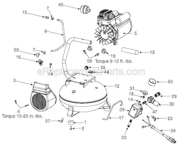
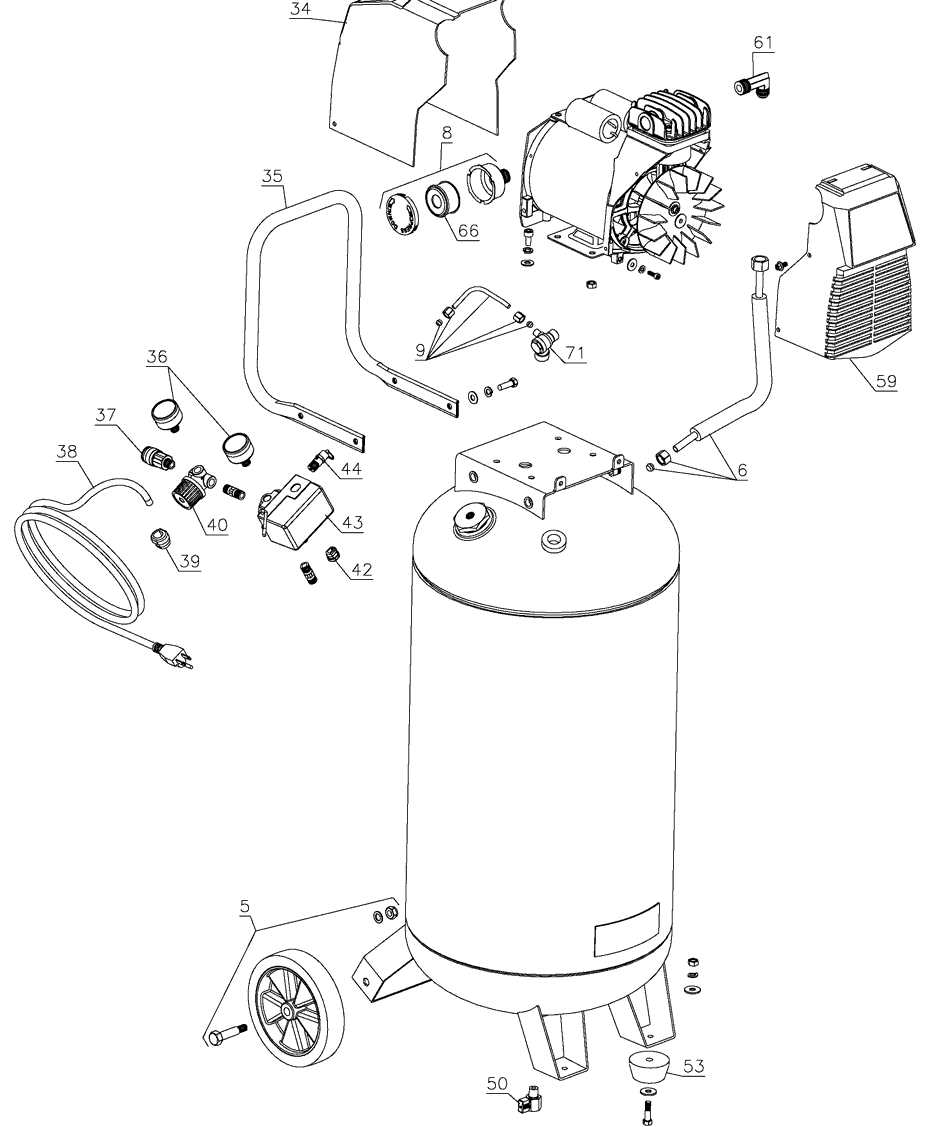
Utilizing a visual guide for maintenance and repairs is essential for efficient troubleshooting. A well-labeled illustration of the device’s internal components helps users identify issues quickly, ensuring that replacements and adjustments are made with accuracy. This guide allows you to understand the placement and function of each component, simplifying the repair process.
To start, locate the part in the illustration that corresponds to the malfunctioning component. This visual reference will help you pinpoint the issue, whether it’s a faulty valve, a worn-out seal, or any other malfunction. Once identified, follow the recommended steps for removing and replacing the part, ensuring you’re using the right tools and techniques for a smooth repair.