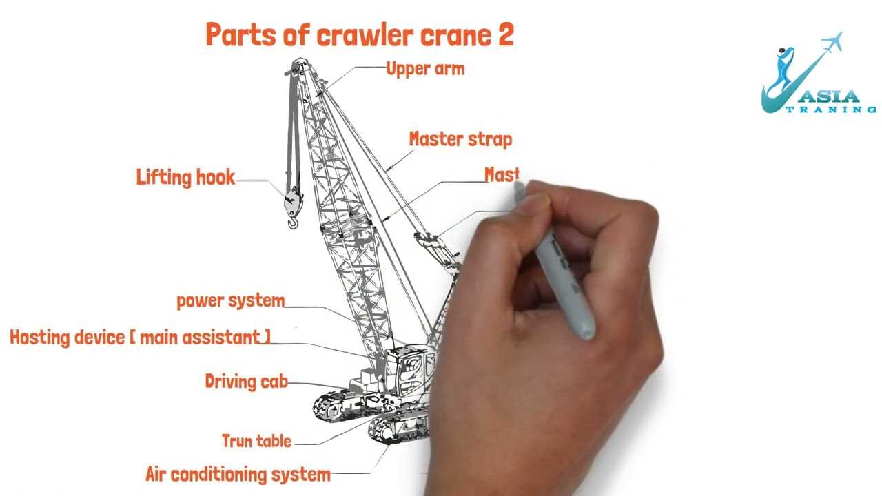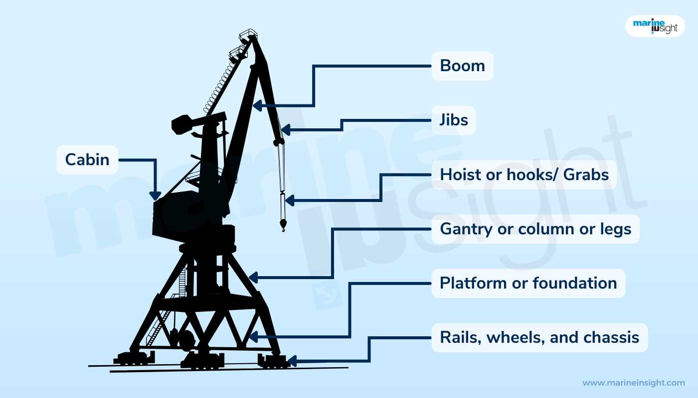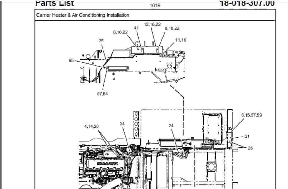
When working with complex lifting equipment, it’s essential to understand the various elements that enable their operation. These machines consist of numerous interconnected components, each playing a crucial role in ensuring smooth and efficient functioning. From the lifting mechanism to the control system, every part must work together harmoniously for optimal performance.
Identifying the key sections of such machines helps operators and maintenance personnel make informed decisions regarding operation, troubleshooting, and repair. Recognizing the function of each element can prevent costly errors and improve safety. Understanding how these parts interact with one another allows for a more in-depth appreciation of the overall system’s efficiency.
Knowing how to interpret visual representations of these machines is equally important. A clear understanding of how each segment is represented provides insight into the machine’s structure and how best to maintain or operate it. With the right knowledge, users can avoid mistakes and ensure a longer lifespan for the equipment.
Understanding Crane Components and Their Functions
In heavy lifting machinery, various systems and elements collaborate to ensure safe and efficient operation. Each segment, from the base structure to the lifting mechanism, serves a specific purpose that supports the entire process of moving and positioning heavy loads. Recognizing these components and understanding their functions is crucial for operators and maintenance personnel alike.
The Structural Framework

The foundation of any lifting system is its structure, which provides the stability necessary for safe operation. This framework supports all other components, including the lifting mechanism and control systems. A well-designed base ensures that the equipment can handle heavy weights without compromising safety. The sturdiness and integrity of this framework are vital to the overall performance.
The Lifting and Control Mechanisms
At the heart of any lifting equipment is the system responsible for raising and lowering loads. These mechanisms rely on a combination of motors, gears, and hydraulic or electric components to function efficiently. The control system, operated by a trained individual, dictates how the machinery moves and interacts with its surroundings. A clear understanding of these systems ensures precise movements and reduces the risk of malfunction.
Key Parts in Crane Mechanism and Design

The functionality of lifting equipment relies heavily on its fundamental components, each of which contributes to the machine’s overall performance and safety. Understanding these elements is essential for anyone involved in the operation or maintenance of such machinery. From the foundation to the lifting system, every part plays a crucial role in ensuring the machine can effectively and safely perform its tasks.
Structural support elements provide the stability necessary for safe operations. The robust framework and base are designed to bear substantial loads while maintaining balance. These support systems are the backbone of the entire apparatus, ensuring it remains steady during operation and under heavy stresses.
Lifting components, such as winches, pulleys, and hooks, are central to the machine’s ability to move large objects. These components work in tandem to lift, lower, and position loads with precision. The design of these elements is critical for both lifting capacity and safety. Effective maintenance of these parts ensures smooth operation and prevents equipment failure.
How to Read a Crane Parts Diagram
Understanding visual representations of heavy machinery can be crucial for both operation and maintenance tasks. These illustrations often contain intricate details, showing the layout and interaction of various components that work together. To properly interpret such visuals, one needs to recognize symbols, understand the scale, and follow the key that explains the elements depicted.
Identifying symbols is the first step in reading these illustrations. Each component is often represented by a specific symbol, and knowing these can help you quickly locate and understand the function of each part. Many manuals provide a legend or key to guide users in identifying these symbols, making it easier to interpret the diagram accurately.
Scale and relationships are also important when reading these visuals. The relative size of each component is often scaled down for clarity, but understanding how these parts interact is crucial for efficient maintenance and troubleshooting. Pay close attention to lines and arrows, which often indicate movement, flow, or connections between different sections of the machine.