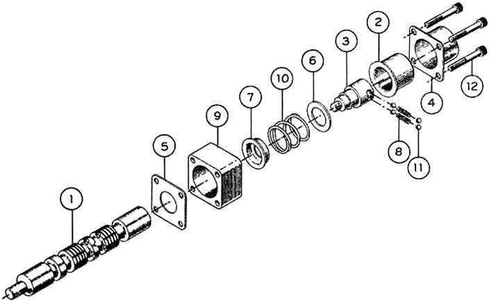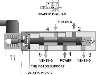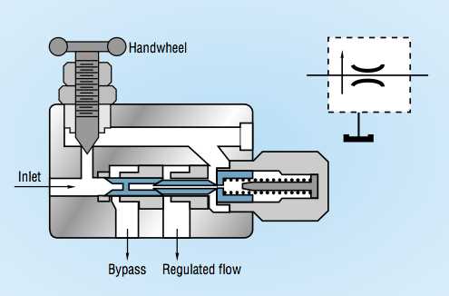
Fluid control mechanisms are essential in various industrial applications, ensuring smooth and efficient operations in complex systems. These mechanisms rely on a variety of components working together to regulate the flow and pressure of fluids. A clear understanding of their layout and functionality is vital for troubleshooting and maintaining optimal performance.
Effective management of fluid systems requires a comprehensive knowledge of how each element contributes to the overall process. The interaction between different components can often be intricate, but with proper insight, users can enhance both efficiency and longevity. Troubleshooting issues or upgrading systems becomes simpler with a solid grasp of how these systems are designed and how each part interacts.
By exploring the intricate design and operation of these systems, it becomes easier to pinpoint areas for improvement and ensure that they function as intended. Through this exploration, we aim to offer clarity on their operation and maintenance, helping you gain a better understanding of their role in various machinery.
Understanding Fluid Control System Components

In any fluid regulation mechanism, each element plays a crucial role in ensuring the efficient control of flow and pressure. These elements interact within a system to manage the direction and force of liquids or gases, allowing precise adjustments and optimal performance. A deep understanding of their functions is vital for anyone working with these systems, whether in maintenance, troubleshooting, or upgrading machinery.
Key components typically include actuators, regulators, and other control mechanisms that are responsible for directing the flow based on specific requirements. These elements are carefully designed to work together seamlessly, ensuring that the system functions as intended, with each part contributing to the overall success of the operation.
Recognizing the design and purpose of each component helps in diagnosing issues, improving system efficiency, and reducing downtime. Understanding how each element contributes to the performance of the entire system is essential for maintaining long-term reliability and effectiveness in fluid-based operations.
How Fluid Control Components Work Together
In a fluid regulation system, various components interact to ensure precise control over the movement and force of liquids or gases. Each part plays a specific role, from directing flow to maintaining pressure within optimal ranges. The seamless cooperation between these elements is critical for the overall efficiency and functionality of the entire mechanism.
The key components communicate through a carefully designed network, where each element adjusts or redirects the flow based on changing conditions. Sensors and actuators work in tandem to monitor and control the fluid’s path, ensuring it follows the intended course. When all the parts are functioning properly, the system operates smoothly, providing the necessary pressure and flow for the task at hand.
Proper coordination between these components is essential for maintaining system reliability. Any malfunction in one part can lead to disruptions, making it crucial to understand how each element contributes to the operation. By analyzing their interaction, users can identify areas of improvement, ensuring better control and performance over time.
Common Issues with Fluid Control Mechanisms

While fluid regulation systems are designed for efficiency, various issues can arise that affect their performance. These problems often stem from wear and tear, improper maintenance, or component failure. Understanding these potential issues helps in identifying and addressing problems before they lead to system failure.
One of the most common issues is leakage, which can occur due to worn seals or faulty connections. This compromises the integrity of the system, leading to pressure loss and inefficient operation. Another frequent problem is blockages, which can occur when debris or contaminants accumulate in the system, restricting the flow of fluid and causing damage to the internal components.
In addition, issues with response time can arise, where the system fails to react quickly or accurately to control signals. This can be caused by faulty sensors or sluggish actuators. Regular inspections and proper maintenance are crucial to identifying these problems early and ensuring the system operates as intended, minimizing downtime and repair costs.