When maintaining or repairing your outdoor machinery, it is essential to have a clear understanding of its internal structure. Knowing the different elements that make up the system helps in identifying issues and ensures efficient troubleshooting. A well-organized guide can make the process easier and more effective for users at any skill level.
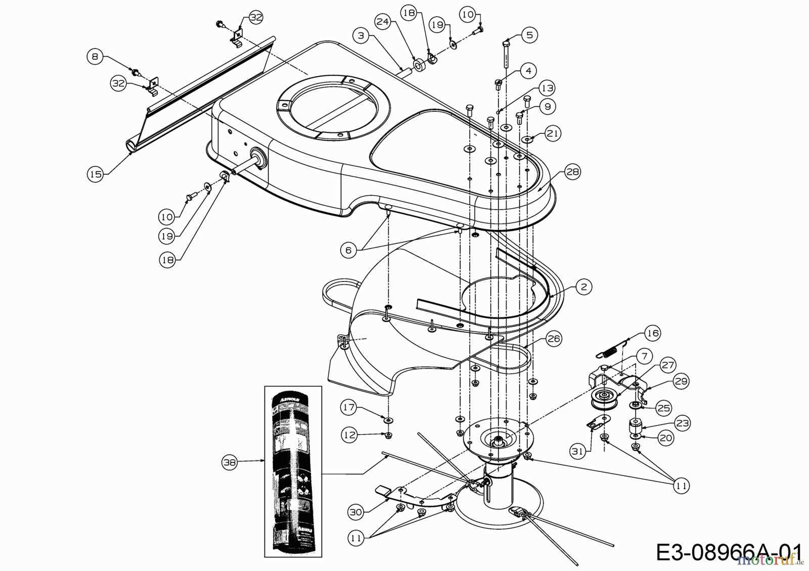
By referring to a detailed visual map, operators can quickly locate the specific sections of the machine that need attention. This tool is crucial for both routine maintenance and addressing more serious malfunctions. Whether it’s for minor fixes or more complex repairs, having a reference at hand ensures that tasks are completed with accuracy and confidence.
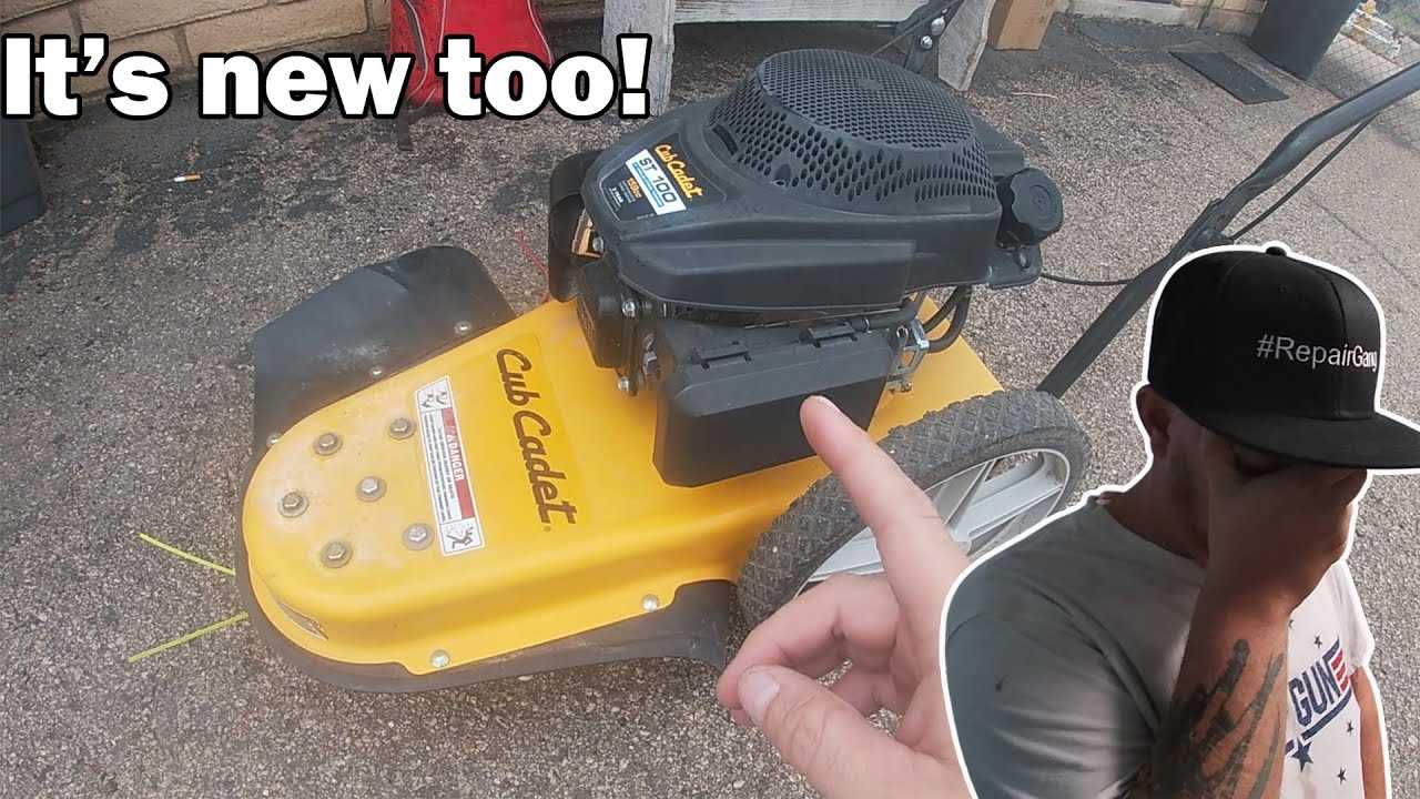
Cub Cadet ST100 Parts Breakdown
Understanding the structure of your lawn equipment is essential for proper maintenance and efficient performance. Each machine consists of several interconnected components that work together to ensure smooth operation. Recognizing these individual elements allows you to quickly assess potential issues and carry out effective repairs.
When breaking down the machine’s construction, it’s helpful to focus on the core sections, from the engine to the operational mechanisms. These areas are key to the overall functionality, and understanding how each part contributes to the performance helps you keep everything running smoothly. Whether it’s for fixing a malfunction or replacing worn-out components, a clear overview of each section aids in making informed decisions.
Understanding Key Components of the ST100

To properly maintain and repair your outdoor machinery, it’s crucial to understand the primary elements that drive its performance. These essential components work together to deliver efficiency and reliability during use. Familiarity with each part’s function allows you to identify issues quickly and make necessary adjustments.
The machine is made up of several key sections, each playing a vital role in ensuring smooth operation. From the power unit to the control mechanisms, every part needs to function optimally. Recognizing these areas helps you perform accurate diagnostics and ensure longevity, making maintenance tasks less daunting and more effective.
How to Use the Parts Diagram Effectively
To maximize the benefits of a detailed visual guide, it’s important to approach it with a clear understanding of how it organizes the different sections of the machine. A well-structured visual reference can save time and reduce confusion during maintenance and repair tasks. By breaking down the components into manageable sections, it helps you focus on specific areas without becoming overwhelmed by the complexity of the equipment.
Start by familiarizing yourself with the layout of the guide, noting the relationships between the key parts. Pay attention to the labels and numbers, as they correspond to the actual components on the machine. Once you understand the reference system, you can easily locate the part you need to inspect or replace, streamlining the troubleshooting process and ensuring precise repairs.