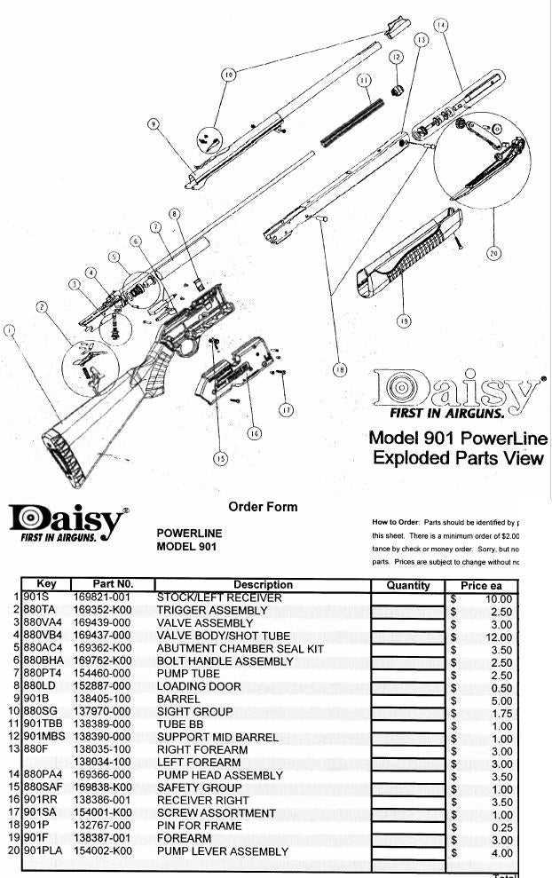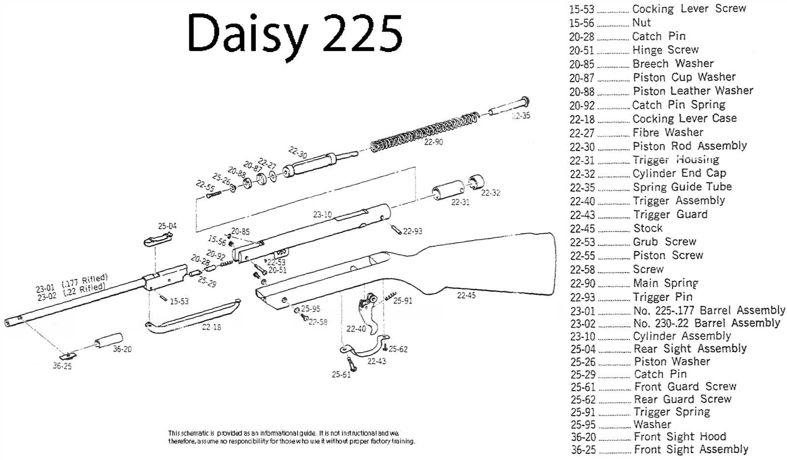
Understanding the internal structure of a mechanical device is essential for both assembly and maintenance. The visual representation of these components allows users to comprehend how different elements interact with one another, providing clarity for repair or modification tasks. This guide is designed to help enthusiasts and technicians alike by offering a clear overview of the device’s inner workings.
By examining a detailed visual map of the components, you can gain insights into the positioning and function of each piece. Whether you’re performing routine maintenance or tackling a specific issue, this visual reference will serve as an invaluable tool in navigating through the assembly.
Familiarizing yourself with the layout is crucial for ensuring proper handling and troubleshooting. Understanding the role of each component can greatly simplify the repair process, allowing for more efficient fixes without unnecessary complications.
Understanding Component Layout
Having a comprehensive view of the internal structure of a device is fundamental for successful assembly and maintenance. A well-organized layout allows users to understand how different elements are interconnected, ensuring that each piece functions as intended within the whole system. This understanding is key to performing repairs or upgrades effectively.
Visualizing Internal Elements

The layout provides a visual guide to all the internal components, helping to identify each part’s role in the operation of the device. By understanding where each element fits and how it interacts with others, you can troubleshoot issues more efficiently. Familiarity with the layout streamlines the repair process, reducing potential errors during assembly or disassembly.
Importance of Proper Understanding
Grasping the arrangement of the internal components aids in better decision-making when handling the device. Whether for preventive maintenance or fixing a malfunction, knowing the layout ensures that no critical component is overlooked. This knowledge is essential for anyone seeking to maintain or enhance the functionality of the system without damaging sensitive components.
Key Components of the Model
Understanding the essential elements of any device is crucial for its effective use and maintenance. Each critical piece within the system serves a specific function, contributing to the overall performance. In this section, we will focus on the most important components that make the device operate smoothly and efficiently.
Main Internal Elements

The following key components are vital for the proper functioning of the system:
- Trigger mechanism: Responsible for initiating the device’s action when engaged.
- Power system: Ensures the efficient transfer of energy required for operation.
- Feeding mechanism: Facilitates the movement of ammunition or components in sequence.
- Safety features: Prevents unintended operations, ensuring user protection.
Additional Supporting Components
Aside from the main elements, the system also relies on several supportive components that enhance its overall efficiency:
- Barrel: Provides the necessary structure for firing mechanisms.
- Grip: Offers secure handling, ensuring user comfort during operation.
- Locking mechanism: Holds specific elements in place during use and prevents unwanted movement.
How to Read a Component Layout
Interpreting a detailed layout of a device can be a crucial skill for understanding its structure and functionality. This type of visual guide not only helps in identifying individual elements but also provides insights into their relationships and interactions within the system. In this section, we will explore how to read and make sense of such a reference.
Identifying Key Elements
When looking at a visual reference, the first step is to recognize the most important components and their placement. Each part is usually represented with a specific symbol or shape. The purpose of this representation is to give you an immediate understanding of what each piece is and where it belongs within the overall framework.
Interpreting Connections and Labels
Connections: Lines or arrows indicate how components are linked together, showing the flow of motion or energy. By following these lines, you can gain insights into how the system operates as a whole.
Labels: Descriptive text or codes are often attached to each element. These labels help you identify specific parts and provide additional information like part numbers, function, or material type. Familiarity with these codes can speed up troubleshooting and repairs.