Accurate measurements are crucial in various fields of engineering and mechanical work. To achieve precision, it is essential to understand the functionality of measuring devices and how their components interact. These tools often come with a visual representation of their internal mechanisms, which can help users interpret the readings and perform tasks efficiently.
Exploring the essential elements of these instruments allows for a deeper understanding of how each part contributes to the overall performance. Recognizing the role of each element enhances one’s ability to operate the tool effectively, ensuring consistent results in different applications.
Mastering the layout of these tools provides valuable insights into their construction, making it easier to troubleshoot and maintain them over time. Whether in quality control or technical setups, familiarity with the internal structure proves invaluable for optimal use.
Understanding the Measuring Tool

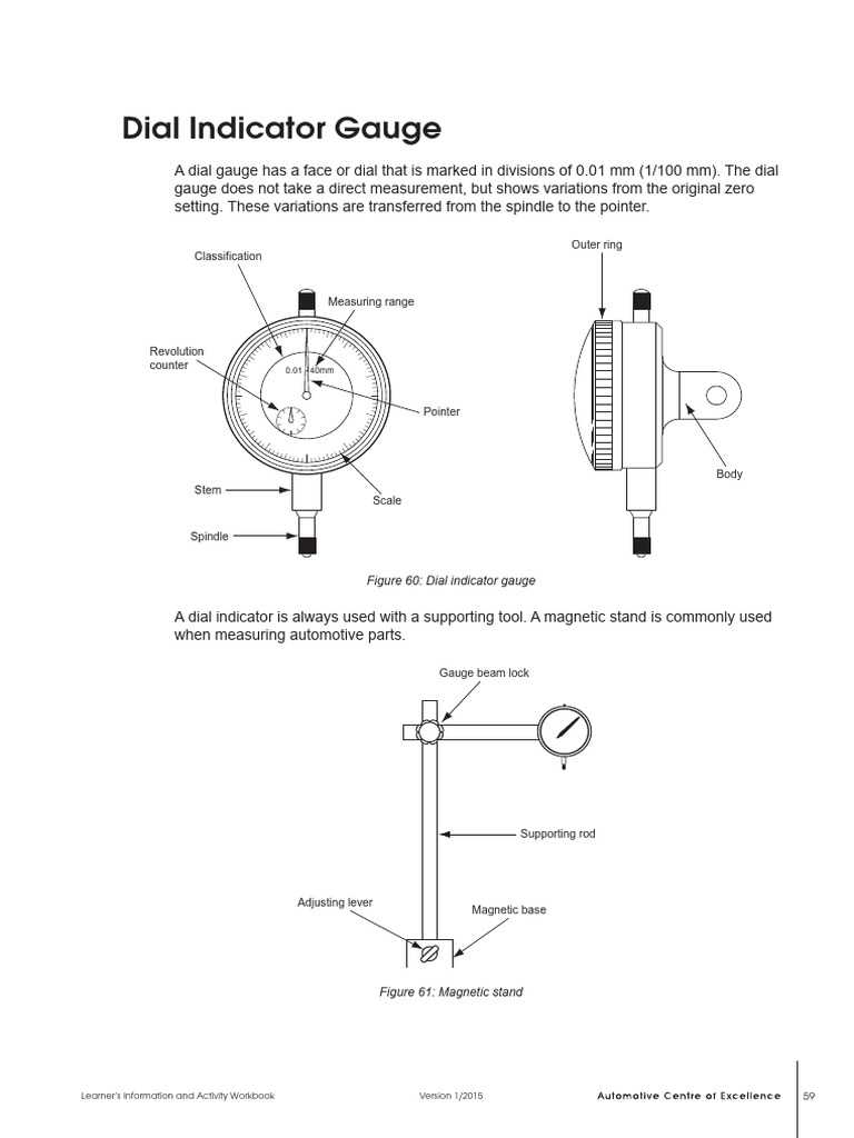
In various fields, precision tools are used to ensure accurate and reliable measurements of surfaces or objects. These instruments are designed to detect even the smallest deviations from a reference point, making them invaluable for quality control, calibration, and mechanical work. The proper understanding of these tools allows users to make the most of their capabilities in a range of tasks, from machinery adjustments to detailed inspections.
One of the key features of such devices is their ability to provide clear readings of minute changes in alignment. This precision is made possible through a carefully crafted mechanism that involves several interacting components. The setup and construction of these tools are critical in ensuring that each reading is as accurate as possible, helping professionals carry out their work with confidence.
Familiarity with the internal elements and their functions is vital to using these devices correctly. Knowing how each section contributes to the overall performance aids in troubleshooting and maintenance. With the right understanding, operators can optimize the tool’s effectiveness and prolong its lifespan.
Key Components of the Measuring Tool
Precision tools are made up of several integral elements that work together to deliver accurate readings. Understanding the function of each component is essential to ensure proper usage and optimal performance. These tools are built to measure fine variations in physical dimensions, with each part serving a specific purpose in the measurement process.
Mechanical Mechanism
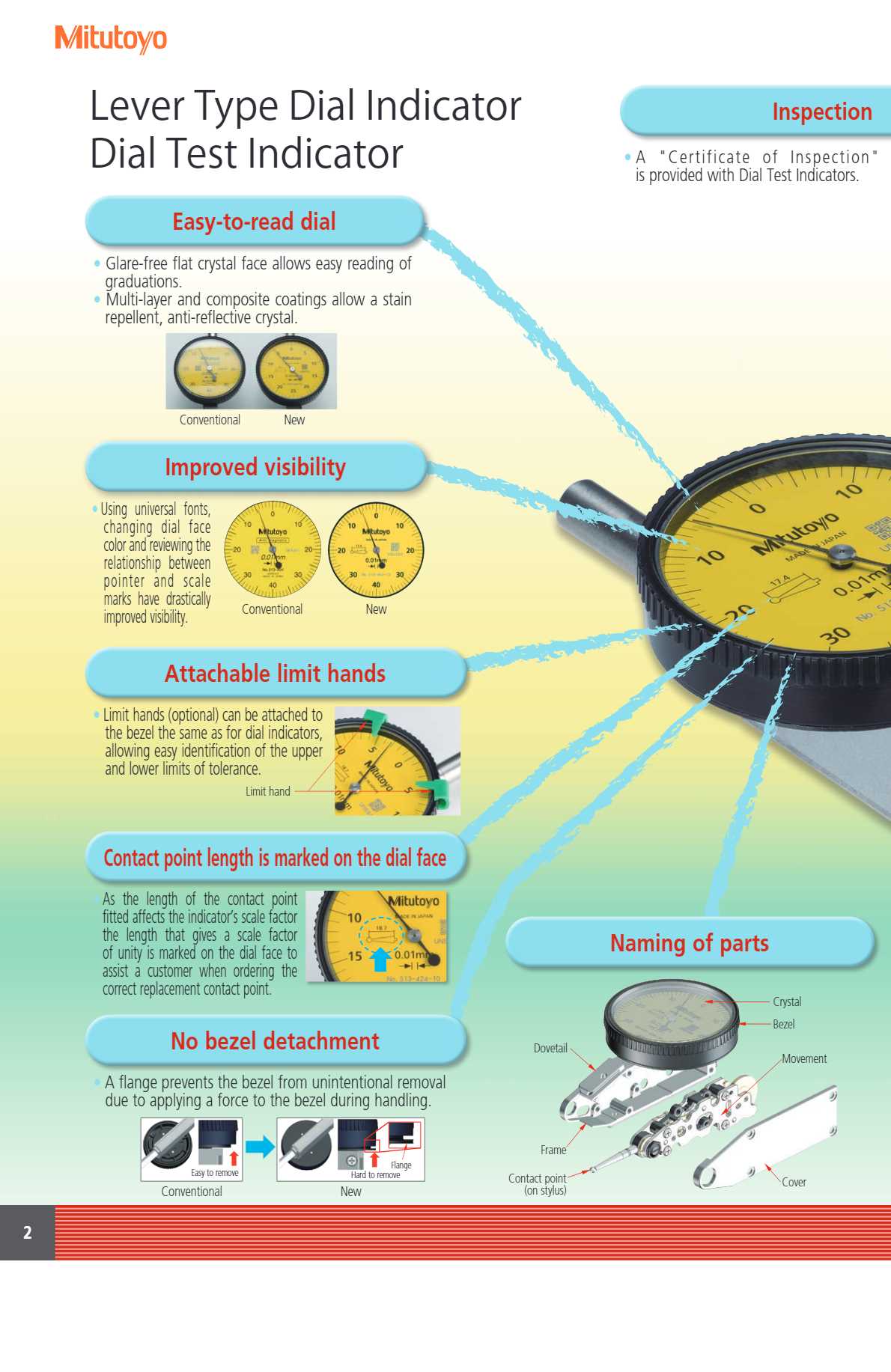
The mechanical structure of the tool is designed to ensure smooth movement and accuracy. The internal spring system or mechanical linkages are responsible for translating minute shifts into readable values. This setup plays a critical role in how the tool captures and records changes, offering the precision needed for high-quality work.
Measurement Scale and Display
Another crucial component is the measurement scale and display, which visually presents the data captured by the tool. This part is responsible for converting the internal readings into an easily interpretable format. The clarity and precision of the scale contribute to the accuracy of the results, allowing users to make informed decisions based on the measurements taken.
How to Read the Measuring Tool Layout

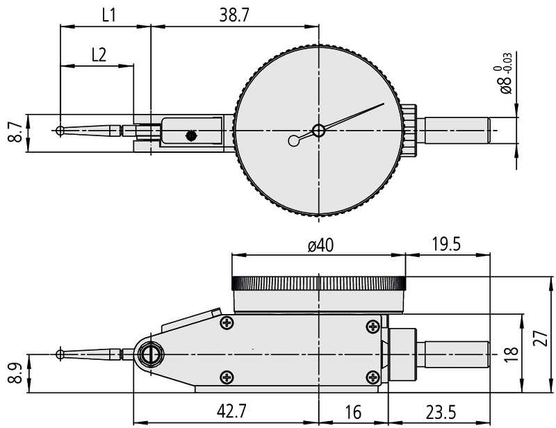
Interpreting the layout of a precision tool is essential for understanding how each component contributes to its overall functionality. The layout serves as a visual guide to the tool’s internal structure, providing insight into how it works and how to troubleshoot or maintain it. Knowing how to read these representations ensures that users can make accurate adjustments and handle the tool correctly for optimal performance.
Identifying Key Components
The first step in understanding any tool layout is identifying the main components. These visual guides usually highlight the most crucial parts, such as springs, arms, and scales. Recognizing these elements helps in understanding how the tool operates and how the different parts interact to produce accurate results. A well-labeled layout allows users to pinpoint the exact location of each component quickly.
Understanding the Movement and Measurements
The next step is understanding how the tool moves and measures. The layout often includes markers or indicators that show the movement range of various components. These indicators are essential for understanding how the tool captures deviations and translates them into readable measurements. By following these guides, users can learn how to read the values and make precise adjustments as needed.