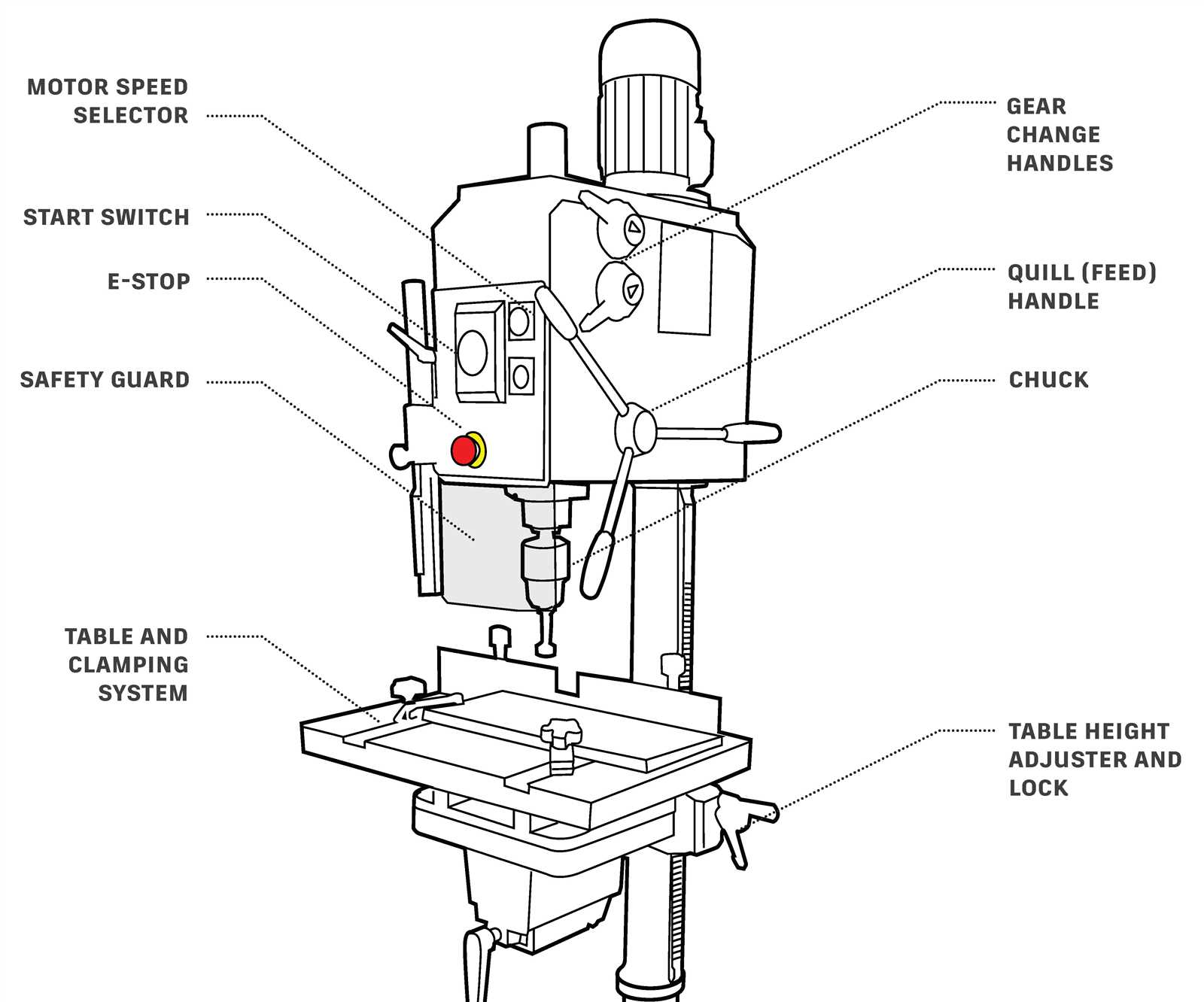
In every workshop, having a clear understanding of how tools are constructed and how their elements work together is crucial for efficient operation and maintenance. Knowledge of the different elements allows users to work with precision and safety. A well-organized tool can dramatically improve your projects, making your work easier and more accurate.
The mechanisms that drive and control the tool’s functionality are often complex. By familiarizing yourself with each crucial segment, you can identify areas that may require maintenance or adjustments. This guide will break down the key features and functionalities, providing a visual reference that can be invaluable for both beginners and experienced users.
Whether you’re assembling, troubleshooting, or upgrading your equipment, understanding its structure will always be beneficial. Having a clear view of each component and how they fit together is the foundation for using your equipment to its fullest potential.
Key Components of a Drill Press
Every functional tool is composed of several core elements that work together to achieve optimal performance. These components are designed to control motion, provide stability, and ensure safety. Understanding these key elements will help users operate the equipment more efficiently and troubleshoot when necessary.
The central mechanism is responsible for controlling the depth and speed of the tool, allowing precise movements. Other essential parts, like the base and column, provide structural support and keep the tool steady during use. The motor, which powers the entire system, is a critical component that determines the overall power and performance of the machine.
Moreover, the control handles, which are used to adjust the position of the tool, offer flexibility in working with various materials. The chuck holds the cutting tool securely, ensuring accuracy in every task. By understanding the function of each segment, users can optimize their experience and extend the lifespan of their equipment.
Understanding the Function of Drill Press Parts
Each component of a tool has a specific role that contributes to its overall performance. Recognizing how these elements interact ensures better control and precision during use. When the user understands the role of each section, it becomes easier to manage tasks and achieve the desired results with minimal effort.
The motor is the driving force behind the entire operation, supplying the energy needed for motion. The column acts as the vertical support, giving the machine its height and providing stability during operation. The base holds everything in place, ensuring that the tool remains steady while in use.
Adjustable features, such as the control handles, allow for customizable movement and positioning, which is crucial when working with different materials or when precise drilling is required. The chuck, which holds the cutting tool, ensures that the tool remains securely in place while performing the task at hand. Understanding how each of these elements functions together will help maximize the tool’s efficiency and extend its lifespan.
How to Identify Parts in a Drill Press Diagram
Understanding the layout of a tool and being able to recognize each element on a visual reference is essential for maintenance, assembly, or troubleshooting. Proper identification allows users to quickly pinpoint areas that may need adjustments or repairs. The challenge lies in accurately matching each part to its corresponding function within the system.
Analyzing the Overview
The first step is to familiarize yourself with the overall structure. Pay attention to the large, prominent components that are likely the most important for operation, such as the base and motor. These parts typically appear as more substantial elements in the diagram, making them easy to spot.
Examining Smaller Elements
Once you have identified the major components, move on to the smaller, more intricate elements like the control handles or chuck. These often require closer inspection to understand their precise location and purpose. Cross-reference the visual with a guide or manual to ensure accuracy in identifying their role within the mechanism.