In any heavy-duty vehicle used for clearing roads, understanding the individual components is essential for ensuring smooth operation and efficient performance. Each element plays a unique role in the overall system, contributing to its ability to tackle challenging tasks.
Whether you are a professional operator or a DIY enthusiast, knowing how these elements fit together helps in troubleshooting, maintenance, and upgrading equipment. By familiarizing yourself with the layout and functionality of each part, you can improve the longevity and reliability of the machine.
Proper maintenance is key to avoiding costly repairs. Recognizing how each component interacts and the function it serves makes diagnosing issues easier and faster, leading to quicker resolutions and less downtime. Understanding the layout ensures that you are always prepared for the task at hand.
Understanding Key Vehicle Components

The effectiveness of any vehicle designed for clearing surfaces relies heavily on the correct functioning of each individual element. These machines consist of various systems, all of which must work in harmony to deliver optimal results. A proper understanding of these components is essential for maintaining efficiency and ensuring smooth operation in the field.
Main Structural Components
The main framework of these vehicles serves as the foundation for all other systems. The structural elements provide the strength necessary to handle the weight and force involved in heavy-duty tasks. Knowing how these components are positioned and supported is critical for both operational performance and maintenance. In particular, the components responsible for lifting, angling, and securing attachments must be well understood for proper control and maneuverability.
Functional Elements and Mechanisms

Beyond the basic structure, there are a number of functional systems that make these machines adaptable to different conditions. Hydraulic systems, motors, and mechanical linkages all play vital roles in how the equipment responds to various challenges. Understanding how each of these systems works individually and together enables operators to troubleshoot and repair issues with ease, ensuring maximum productivity in demanding environments.
How to Read a Vehicle System Layout

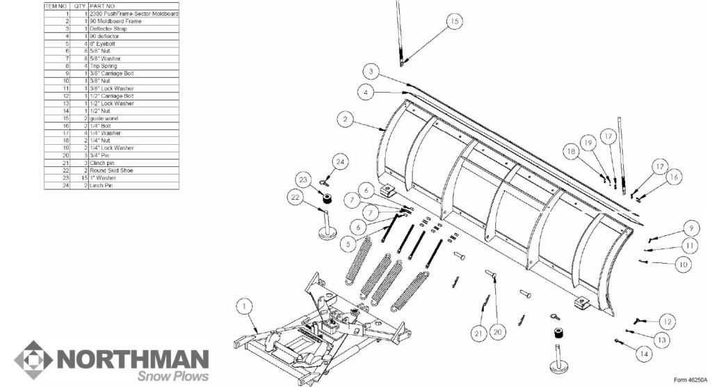
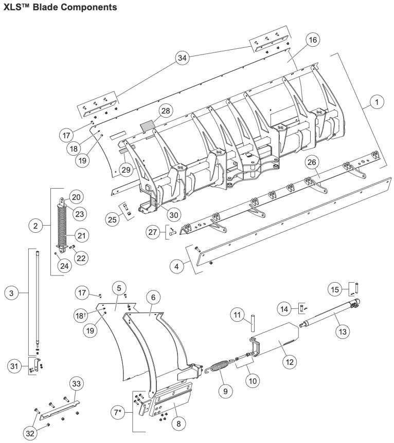
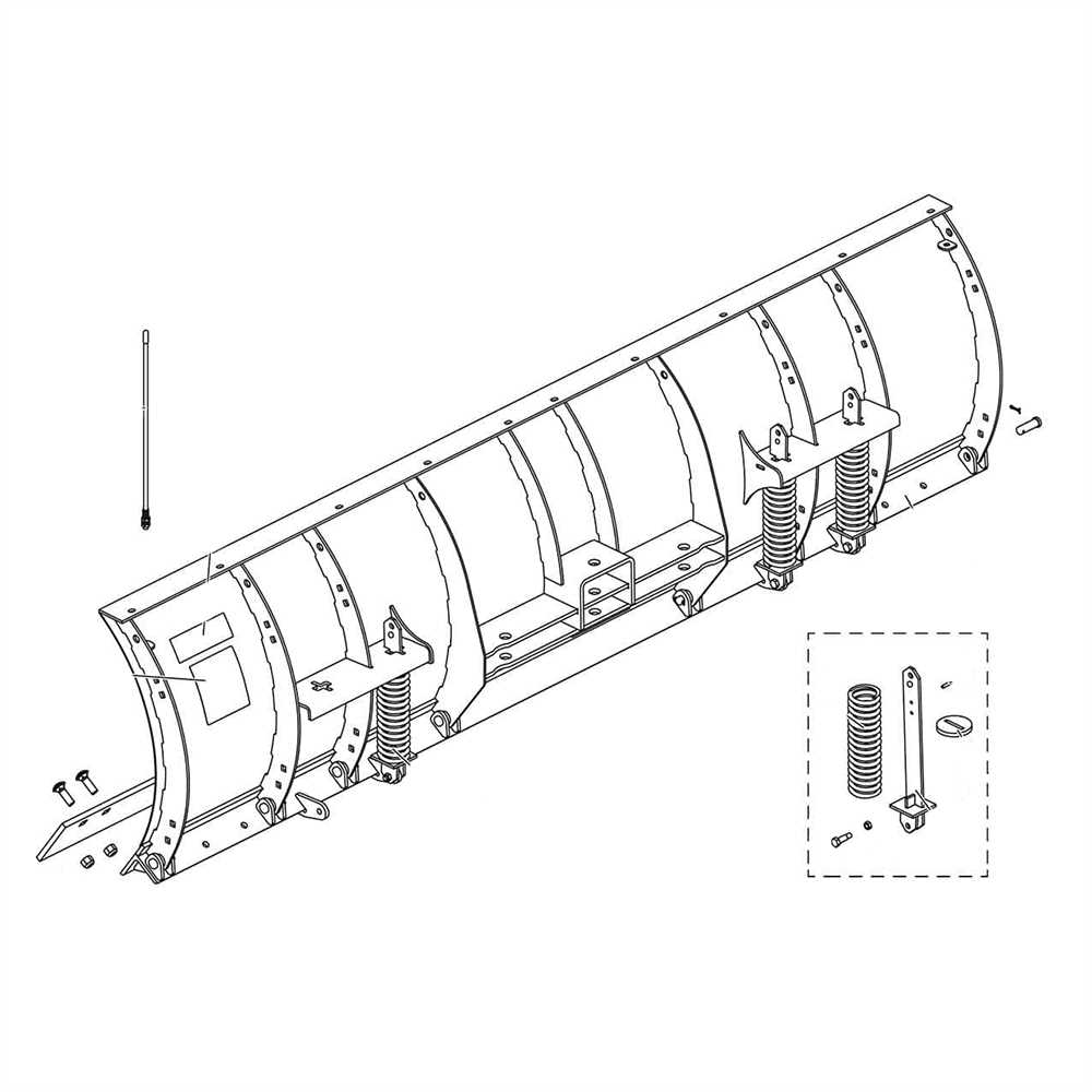
Interpreting the layout of complex vehicle systems can be a daunting task, but with a clear approach, it becomes easier to understand the function and arrangement of each component. These layouts offer detailed illustrations that highlight the position and connection of individual elements, allowing for a deeper insight into their operation. Properly reading these diagrams ensures efficient troubleshooting and maintenance.
Understanding Symbols and Labels
Most vehicle system layouts use standardized symbols to represent different parts and connections. Recognizing these symbols is the first step in interpreting the layout. Here’s what to focus on:
- Shapes: Different shapes represent various parts, such as valves, connectors, or motors.
- Lines: Solid lines usually indicate physical connections, while dashed lines show movement or fluid paths.
- Labels: Ensure you read all labels carefully as they provide essential details about each part’s specifications and function.
Step-by-Step Approach to Reading
When viewing a system layout, follow these steps to gain the most information:
- Start with the main components, usually at the center or bottom of the diagram.
- Identify the flow of connections between parts, following the lines to understand how energy or material moves through the system.
- Note any markings that indicate the function or capacity of a component, such as pressure levels or load-bearing specifications.
By following these guidelines, you can efficiently read and interpret any system layout, gaining valuable insights into how each component contributes to the overall operation.
Common Components of Clearing Equipment
Heavy-duty vehicles designed for clearing surfaces consist of a variety of essential elements that ensure smooth and efficient operation. Each component serves a unique function, contributing to the overall performance and capability of the machine. Understanding these key components is crucial for proper maintenance, repair, and effective operation in challenging conditions.
Hydraulic Systems and Actuators
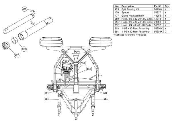
The hydraulic system plays a central role in the movement and control of these vehicles. It powers the lifting and angling mechanisms, allowing operators to adjust the equipment for different tasks. Hydraulic pumps, cylinders, and hoses are crucial parts of this system. They work together to provide the necessary force for the equipment to perform its function, ensuring the system’s reliability is key to maintaining performance.
Mounting and Attachment Elements

Another essential group of components includes those responsible for mounting and securing various attachments. These parts enable the quick connection of different implements, allowing the machine to adapt to a range of tasks. Brackets, mounts, and fasteners are critical for keeping attachments secure during operation, while ensuring they can be easily changed when needed. These elements must be checked regularly for wear and tear to avoid operational issues.
Understanding the role of each component and how they work together helps ensure that the machine is functioning at its highest capacity and ready to handle any task effectively.