Maintaining the functionality of your GE appliance requires a clear understanding of its internal structure. Knowing how the various components work together is essential for troubleshooting and ensuring optimal performance.
Each unit contains several key elements that play specific roles in its operation. By familiarizing yourself with their locations and functions, you can efficiently address common issues and carry out effective maintenance tasks.
With this knowledge, you will be better equipped to identify problems and take appropriate action. Whether you’re performing regular upkeep or repairing a malfunction, understanding the internal workings is crucial for longevity and efficiency.
Understanding the Key Components of GE Dehumidifiers

To ensure the smooth functioning of your GE appliance, it is important to be familiar with its key internal components. Each element serves a specific role, contributing to the overall efficiency and performance of the unit. Understanding how these parts interact allows for better maintenance and quicker identification of potential issues.
Essential components work together to regulate moisture levels and control airflow within the system. These elements are designed to perform specialized tasks, from controlling humidity to protecting the unit from wear and tear. Familiarity with these components helps users troubleshoot problems and make informed decisions during repairs.
In this section, we will explore the core components, their functions, and how they contribute to the effectiveness of your GE appliance. Understanding their roles will help you maintain the unit in optimal condition and extend its lifespan.
How to Read the GE Dehumidifier Parts Diagram
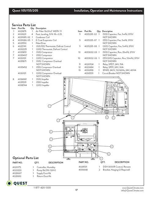
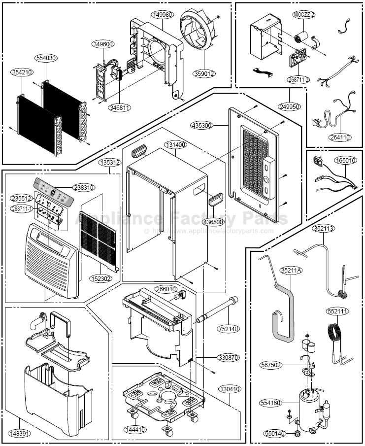
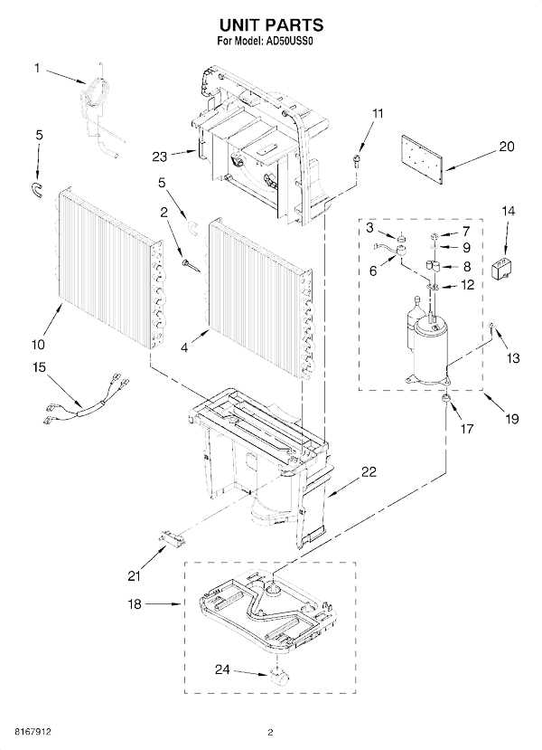
Understanding the internal layout of your GE appliance requires knowing how to interpret its schematic. These visual guides offer a clear representation of the unit’s components and their arrangement. Learning to read these diagrams can significantly simplify the process of troubleshooting and repair.
Identify the Key Sections

Start by locating the main sections of the unit, such as the control system, airflow pathways, and moisture management components. Each section is typically labeled to make identification easier. Recognizing these areas will help you focus on specific issues when needed.
Follow the Connections and Labels

The connections between components are usually indicated by lines or arrows. These visual cues show how different elements interact, and understanding them is crucial when diagnosing faults or replacing specific parts. Labels often provide additional information, such as part numbers or functions, for easier reference.
Common Issues and Repairs for GE Dehumidifier Parts
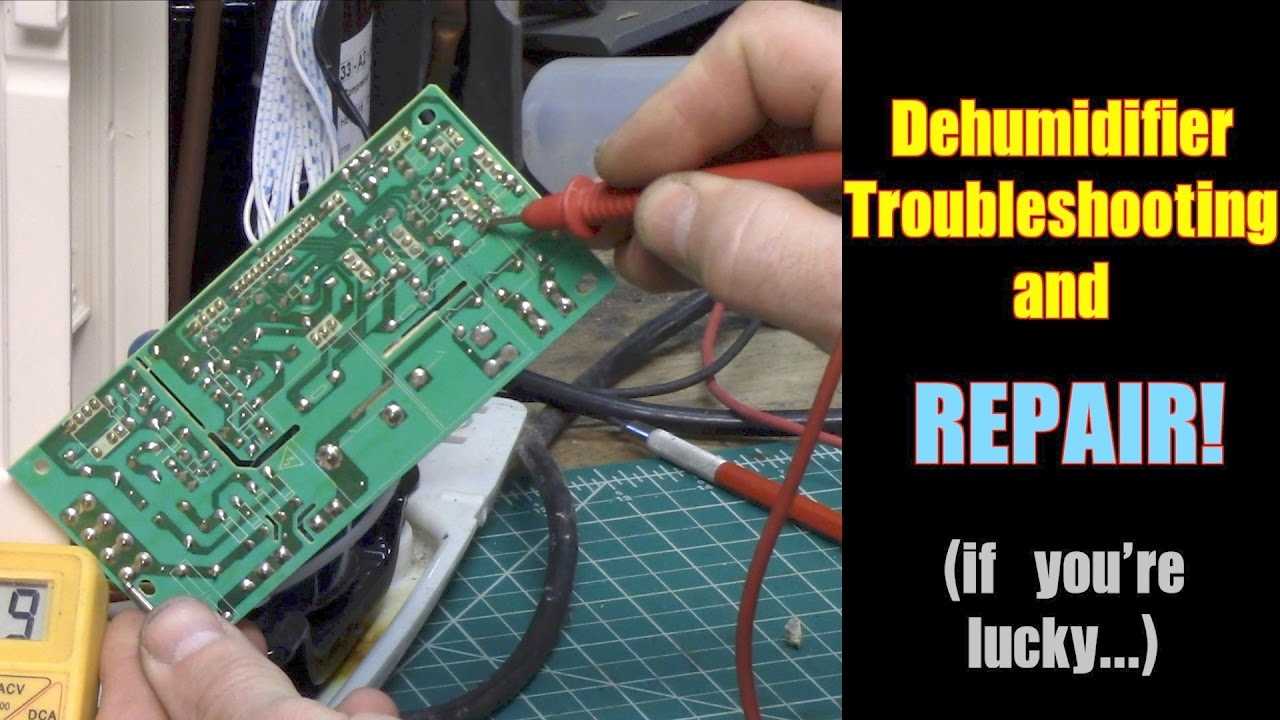
When your GE appliance is not performing as expected, it is often due to issues within its internal components. Understanding these common problems can help in diagnosing and addressing faults effectively. Many issues can be resolved with basic repairs or part replacements, improving the unit’s overall efficiency.
Clogged or Dirty Filters
One of the most frequent problems is a clogged or dirty filter. Over time, dust and debris can accumulate, restricting airflow and causing the system to overheat or lose efficiency. Regular cleaning or replacing the filter will help maintain proper function and prevent potential damage to other components.
Faulty Fan Motor
If the airflow seems inadequate or the appliance makes unusual noises, the fan motor might be malfunctioning. A faulty motor can cause poor air circulation, leading to decreased performance. In many cases, the motor can be replaced to restore the system’s functionality and ensure it operates smoothly.