Efficient maintenance of your equipment relies on having a clear understanding of its internal elements and how they function together. Knowing the essential components and their layout allows users to make informed decisions about repairs and upgrades. A visual representation of the system can simplify troubleshooting and maintenance, ensuring smooth operation over time.
For anyone working with high-performance machinery, it is crucial to become familiar with the main components. Whether you’re conducting repairs or simply performing routine upkeep, understanding how each part works and fits into the whole system can make a significant difference. This guide will help you navigate through the different elements and offer practical advice for maintaining optimal performance.
Accurate identification of parts and their proper maintenance is key to preventing downtime and extending the lifespan of your equipment. Regular inspection and timely repairs can prevent major breakdowns, saving both time and money in the long run.
Understanding Key Components
To ensure the longevity and functionality of any equipment, it’s essential to familiarize yourself with its internal components. Each element plays a crucial role in how the system operates, and recognizing their individual purposes is key to maintaining optimal performance. Understanding the layout and interaction of these components can streamline troubleshooting and repair tasks.
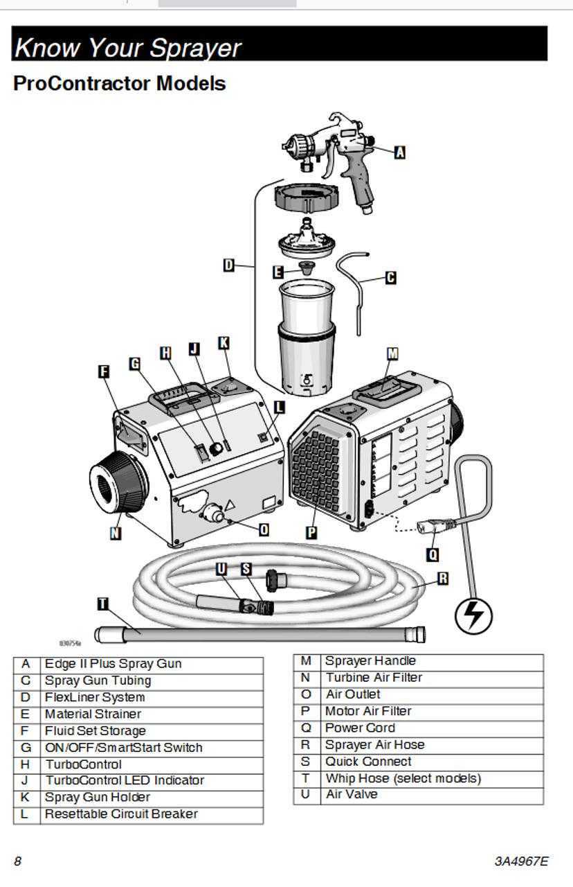
The primary components of the machine are designed to work together seamlessly, and recognizing these components can save time when identifying issues. Here are the core elements that make up the system:
- Motor – The powerhouse responsible for driving the machinery and ensuring consistent operation.
- Fluid System – Contains the components that manage the flow of liquid, including hoses, valves, and filters.
- Spray Gun – The interface used by the operator to control the dispersion of material.
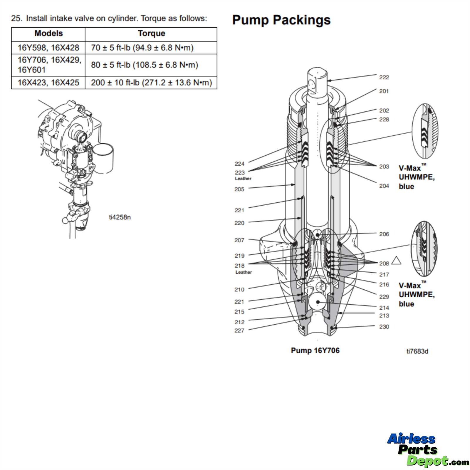
- Pump – Moves material through the system, ensuring a continuous and efficient flow.
- Pressure Control – Regulates the pressure at which material is dispensed, ensuring even coverage and avoiding damage.
Knowing these elements helps in understanding the overall performance of the machine. Each component requires specific care and attention, which will be covered in detail later. Regular inspection of these crucial components is vital for preventing wear and ensuring smooth operation.
Key Parts of the Equipment
Understanding the critical components of any machinery is essential for ensuring its effective operation. These key elements work in harmony to deliver optimal performance and maintain the efficiency of the entire system. Identifying these parts is the first step in troubleshooting, maintenance, and repairs, allowing operators to address specific needs as they arise.
Essential Components
Among the most important components of this equipment, there are several that significantly impact performance. These elements include:
- Motor Assembly – Drives the system and ensures consistent functionality through power generation.
- Pressure Regulator – Maintains the necessary pressure levels for smooth operation.
- Fluid Delivery System – Controls the movement of liquids throughout the machine, from intake to dispensing.
- Spray Mechanism – The interface used for material application, ensuring precise and controlled distribution.
- Hoses and Filters – Manage the fluid flow and ensure contaminants do not interfere with operation.
Supporting Elements

There are several supporting parts that assist the key components in achieving their tasks. These include:
- Gaskets and Seals – Prevent leakage and maintain proper sealing throughout the machine.
- Valves – Regulate the flow of material and control the direction of pressure within the system.
- Pump Assembly – Facilitates the movement of fluids through the system, maintaining the necessary pressure for operation.
Regular maintenance and timely repairs of these essential parts can ensure the machine remains reliable and performs at its best for extended periods.
How to Use the Parts Diagram
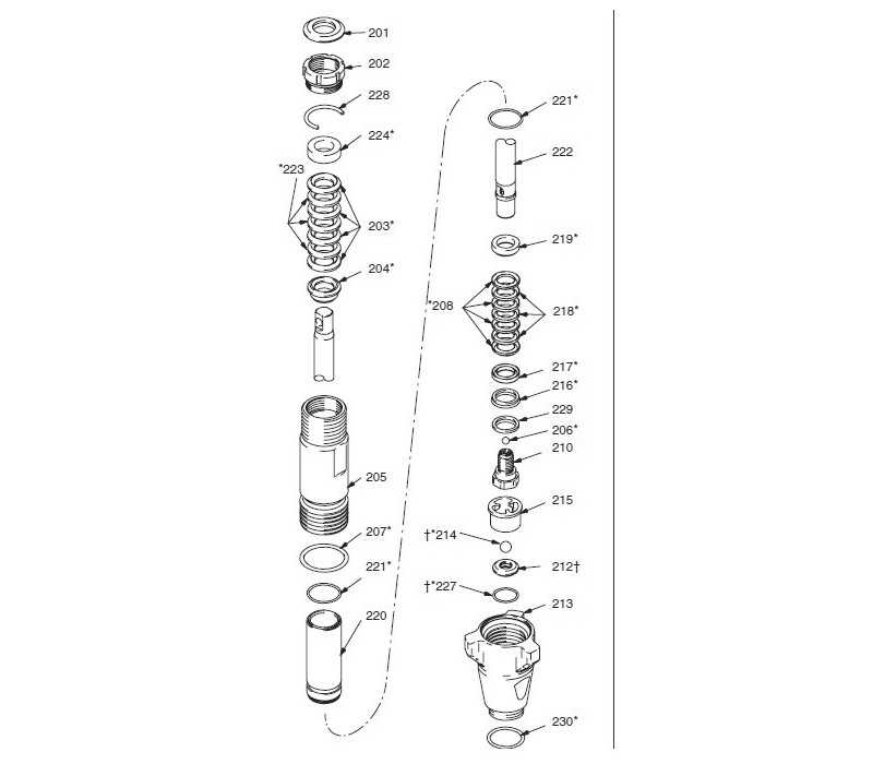
Having a clear visual guide for understanding the machine’s components can make maintenance and repairs much easier. A well-detailed illustration helps users quickly locate specific elements and understand how they fit into the overall system. By using this visual tool, you can efficiently identify issues, order replacements, and perform adjustments or repairs with confidence.
Identifying Key Components
The first step in using the visual guide is to familiarize yourself with the layout. The diagram will typically feature all essential elements labeled clearly, allowing you to pinpoint parts with ease. Pay close attention to the orientation and placement of each component, as this will help in understanding the assembly and any potential issues related to positioning or alignment.
- Locate each item by its designated label.
- Refer to the guide when disassembling or reassembling the machine.
- Ensure proper placement based on the visual representation.
Using the Diagram for Troubleshooting
When a problem arises, refer to the visual guide to identify the component that may be causing the issue. By cross-referencing the machine’s symptoms with the diagram, you can often pinpoint the faulty part more quickly. This process reduces downtime and improves repair accuracy.
- Compare the malfunctioning area with the diagram.
- Check for any signs of wear or damage on the highlighted components.
- Consult the visual guide for part numbers and specifications when ordering replacements.
Utilizing the diagram as a reference ensures more effective troubleshooting, maintenance, and repairs. It simplifies the process of finding the right parts and helps avoid unnecessary mistakes during disassembly or reassembly.
Reading and Interpreting the Diagram

Properly understanding a visual representation of your equipment’s components is crucial for effective maintenance and repair. These illustrations are designed to highlight key elements and their relationships, allowing you to gain a clear picture of the system’s structure. Interpreting the diagram correctly enables you to pinpoint potential issues, determine the exact components needed for repairs, and ensure the machine operates efficiently.
Each part in the visual guide is typically marked with labels, arrows, and numbers that correspond to a specific component or system. To interpret the guide accurately, follow these steps:
- Examine Labels and Numbers: Each component is usually labeled with a number or letter that corresponds to a part list, which will provide more detailed information about the item.
- Check for Orientation: Ensure that the parts are shown in the correct orientation as they would be in the actual setup, to avoid confusion during reassembly.
- Follow Arrows: Arrows and lines on the diagram often indicate how parts are connected or how fluid or material flows through the system. Pay attention to these connections to understand functionality.
By following these guidelines, you can efficiently interpret the diagram, making repairs and replacements quicker and more accurate. It ensures that the correct components are handled and placed properly, reducing the chance of errors during maintenance.
Common Maintenance Tips for Your Equipment
Routine upkeep is vital for maintaining the efficiency and longevity of any machinery. Regular checks, cleaning, and replacements can prevent major issues, reduce downtime, and enhance overall performance. By following a consistent maintenance schedule and addressing small problems early, you can ensure that the equipment remains in optimal condition.
Routine Checks and Cleaning
Regularly inspecting and cleaning key components can help identify potential issues before they develop into costly repairs. Simple tasks, such as clearing debris, checking fluid levels, and inspecting hoses for wear, are essential for avoiding malfunction.
| Task | Frequency | Purpose |
|---|---|---|
| Inspect Hoses | Every 50 hours | Prevent leaks and blockages |
| Clean Filters | Every 100 hours | Ensure smooth fluid flow |
| Check Fluid Levels | Before every use | Ensure proper function and efficiency |
Replacing Worn Components
Over time, certain components are bound to experience wear and tear. Timely replacements of essential parts, such as seals, filters, and seals, can prevent further damage and maintain smooth operation. Always use quality replacements to ensure the machine runs as expected.