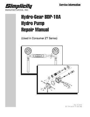
When working with complex hydraulic systems, it’s essential to have a clear understanding of their internal mechanisms. These systems rely on a variety of interconnected elements that work together to provide efficient performance. Identifying each part and understanding its function can significantly improve maintenance and troubleshooting tasks.
Recognizing the roles of individual components and how they interact within the system is key to ensuring optimal functionality. A well-organized layout of these elements helps technicians quickly identify any issues and make informed decisions during repairs or upgrades.
Familiarizing yourself with the structure of these intricate systems can save time and resources. In this article, we will explore the critical components that form the backbone of these systems and offer insights into how they operate together to achieve precise and powerful movements.
Understanding Hydraulic System Components
In any hydraulic-driven mechanism, a range of elements work in unison to ensure smooth and efficient operation. Each component plays a specific role, contributing to the overall functionality of the system. Familiarity with these components allows for a better grasp of how the system operates and how to troubleshoot when issues arise.
The central components typically include the pumps, motors, valves, and control units, each with distinct functions that facilitate movement and pressure regulation. Understanding how these elements interact and how their roles affect one another is essential for anyone maintaining or repairing hydraulic systems.
Properly identifying and analyzing the different sections of the system can also help extend the lifespan of machinery. By recognizing wear patterns or identifying failing components early, preventative maintenance can be conducted to avoid more costly repairs in the future.
How to Read Hydraulic System Schematics
Understanding the layout of a hydraulic system is essential for proper maintenance and repair. Schematics serve as visual representations of the system, showing how the various components are connected and interact. Reading these visuals accurately can guide technicians in identifying potential issues and understanding the system’s overall functionality.
When interpreting these illustrations, it’s important to familiarize yourself with common symbols that represent different components such as pumps, valves, and motors. Each symbol provides information about the function and relationship of the elements within the system.
Additionally, flow arrows and pressure indicators often appear in these schematics to show the direction of fluid movement and the points at which pressure changes. Understanding these aspects will allow for quick identification of potential blockages or pressure irregularities that may affect system performance.
Common Hydraulic System Components and Their Functions
In every hydraulic system, certain elements are crucial for ensuring efficient operation. These components are responsible for controlling fluid flow, regulating pressure, and converting energy to perform specific tasks. Understanding the role of each part can help improve maintenance practices and extend the system’s lifespan.
Pumps
Pumps are the heart of the system, responsible for generating the necessary flow of fluid under pressure. They convert mechanical energy into hydraulic energy, enabling movement and force transmission throughout the system. A properly functioning pump is essential for maintaining pressure and consistent fluid flow.
Valves
Valves control the flow and direction of fluid within the system. They regulate pressure, direct the movement of the hydraulic fluid to different components, and ensure the system operates according to the desired parameters. Some valves are designed to relieve pressure, while others direct the flow to motors or cylinders.