Proper maintenance and efficient operation of any mechanical equipment rely on a clear understanding of its internal structure. For air compression systems, having a thorough knowledge of the key components and how they fit together is essential. This allows for effective troubleshooting and ensures the longevity of the equipment.
Identifying individual elements in a compressor system can be a complex task without a detailed reference. It’s important to familiarize yourself with the parts that make up the machine, as well as their respective functions. This understanding enables users to diagnose potential issues quickly and perform necessary repairs.
Whether you’re a technician or simply looking to enhance your knowledge, knowing the breakdown of critical components is invaluable. It provides a solid foundation for maintaining optimal performance and minimizing downtime. With the right tools and information, managing the system becomes more straightforward and less prone to error.
Understanding the Air Compressor Components

Every mechanical system operates through the seamless interaction of various components, each serving a specific function to ensure smooth operation. In air compression machinery, this complex network of parts plays a crucial role in converting electrical energy into pressurized air for various industrial and commercial uses. Gaining a deeper understanding of how these elements interact with each other is essential for proper maintenance and efficient operation.
The main elements of a compression unit include the motor, pistons, cylinders, and valves, all of which must work in harmony to produce the desired output. Each component is designed with precision, and knowing their individual roles allows technicians and operators to identify potential problems before they escalate. Regular inspection and familiarity with these critical parts can also help extend the lifespan of the equipment.
Comprehending the layout of these elements is particularly beneficial when troubleshooting issues. For example, understanding the flow of air through the system and recognizing how changes in one component can affect the others empowers users to perform more accurate repairs. This knowledge ultimately leads to more efficient performance, reduced maintenance costs, and minimal downtime.
How to Read the Compressor System Breakdown
Understanding how to interpret the visual representation of a machine’s internal structure is essential for effective maintenance and repair. A well-structured schematic provides a clear view of how the components are connected and interact with one another. By following the guide, technicians can easily identify each individual element and its placement within the system.
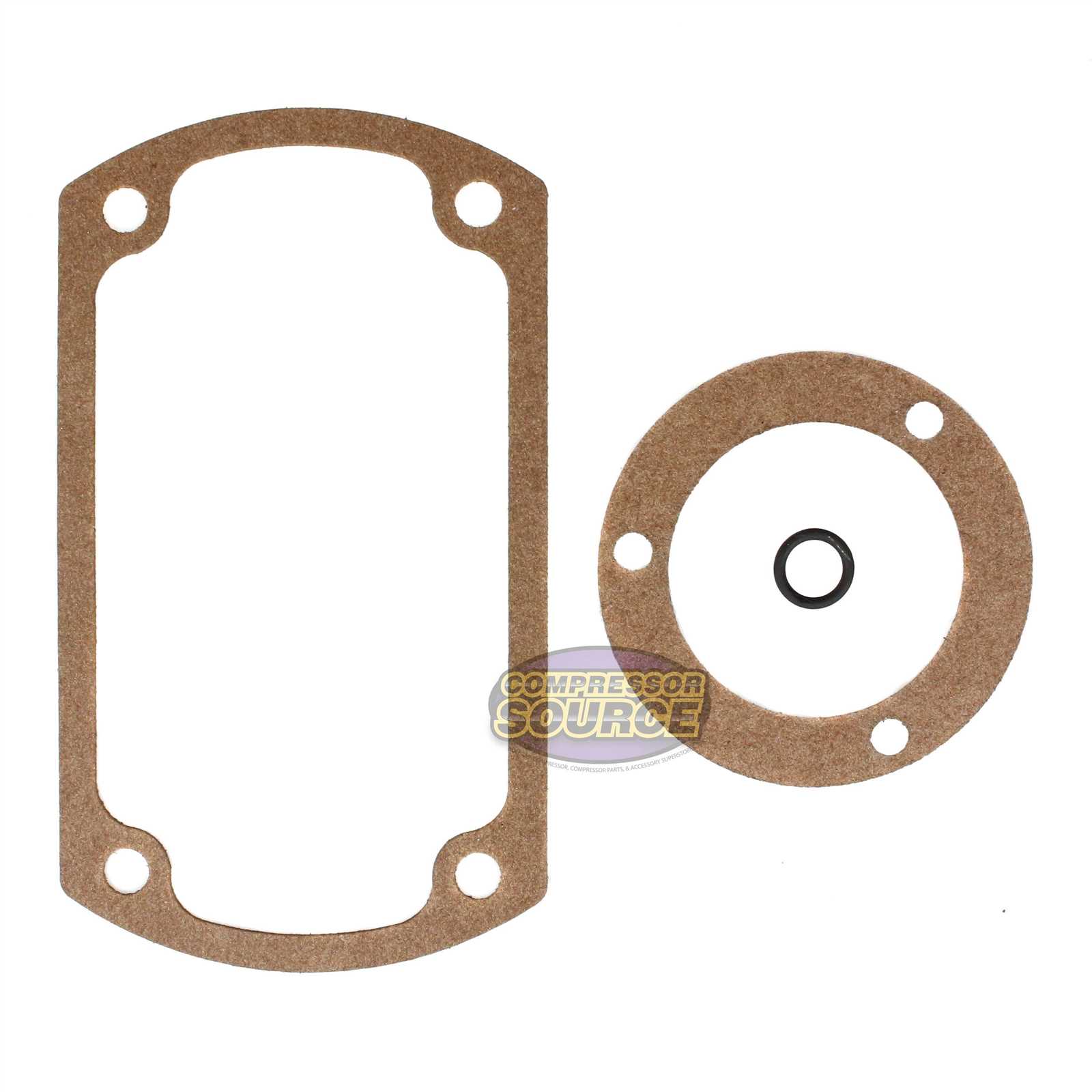
Start by identifying the major components such as the motor, valves, and pressure switches. These are typically shown in a more prominent manner to highlight their importance in the overall functioning. Once you have identified these key parts, you can focus on the smaller elements that support their operation, such as piping, connectors, and seals.
Each line in the representation corresponds to a specific connection or flow path, often with annotations to explain the exact function or material of the parts. Pay close attention to the labels and directional arrows as they indicate how air or fluid moves through the system. By becoming familiar with the visual symbols and their meanings, you can efficiently navigate the breakdown and troubleshoot any issues.
Common Issues and Solutions for Compressor Components
Mechanical systems are prone to wear and tear over time, and air compression units are no exception. Understanding the most common problems that may arise with the internal components can help in diagnosing issues quickly and taking corrective actions before they lead to more serious damage. Below are some of the frequent challenges encountered and their possible solutions:
- Air Leaks: Leaks in the system can reduce efficiency and cause the unit to work harder than necessary. These are often due to worn-out seals or damaged hoses.
- Solution: Inspect the connections and seals regularly. Replace any damaged components promptly to maintain optimal performance.
- Overheating: Excessive heat can cause components to fail prematurely, often due to inadequate cooling or overuse.
- Solution: Ensure proper ventilation around the unit and check the cooling system for any blockages. Consider reducing the workload if the compressor operates for extended periods.
- Poor Airflow: If the compressor isn’t producing the desired air pressure or volume, the problem may lie within the airflow system.
- Solution: Check for any obstructions in the air intake or exhaust and ensure filters are clean. Replacing clogged filters can significantly improve airflow and efficiency.
- Excessive Vibration: Unusual vibrations can be a sign of unbalanced components or worn-out parts.
- Solution: Inspect the motor, pistons, and other rotating elements. Replace any damaged or misaligned parts and ensure that everything is properly balanced.
Regular maintenance and early detection of these issues can extend the lifespan of the compressor system and help maintain its efficiency. By addressing minor problems promptly, operators can avoid costly repairs and downtime.