Maintaining agricultural machinery is crucial for ensuring optimal performance and longevity. Understanding the different components of a mower-conditioner and how they work together can help operators make informed decisions when performing maintenance tasks or repairs. Knowing the design and function of each element can prevent unnecessary wear and improve efficiency during operation.
In this guide, we explore how to identify key sections of a mower-conditioner, from the cutting mechanism to the drive system. Familiarizing yourself with these parts will assist in troubleshooting and help you understand the necessary upkeep for a smooth-running machine.
Whether you’re a seasoned farmer or just starting out, having a clear view of the machinery layout is essential for reducing downtime and improving the effectiveness of maintenance. This article will provide the insights needed to confidently navigate the technical details of the equipment.
Understanding Mower-Conditioner Design
The design of a mower-conditioner plays a crucial role in its efficiency and durability. Each component is carefully engineered to work in harmony, ensuring smooth operation during the harvesting process. A solid understanding of the layout and function of these elements helps users perform better maintenance and troubleshooting, ultimately extending the machine’s service life.
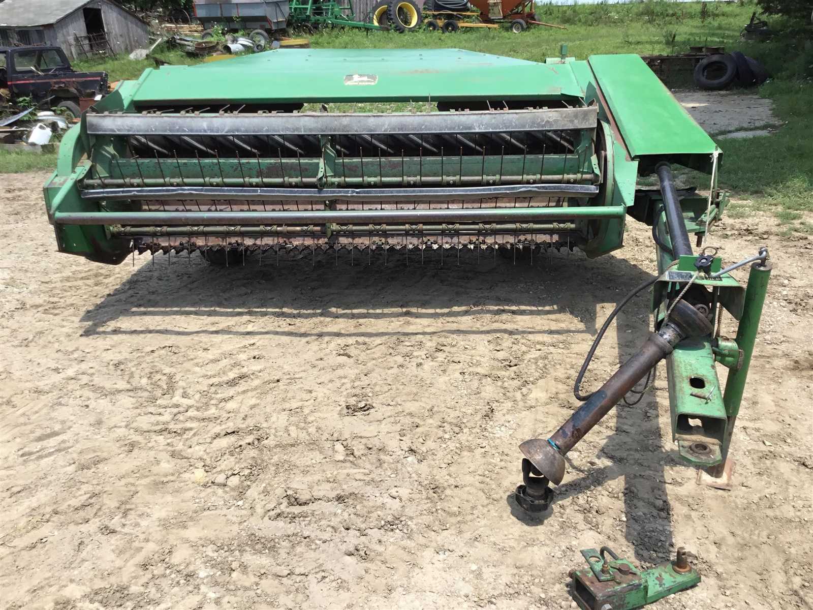
At the core of the machine’s design is the cutting mechanism, which is responsible for quickly and cleanly severing crops. Surrounding this, the drive system and power transmission components ensure that the movement is precise and consistent. Additionally, the conditioner’s system works to efficiently handle the crop material post-cutting, making it ready for further processing or storage.
Familiarity with how each section interacts will allow operators to quickly identify potential issues, adjust settings appropriately, and improve overall performance. By breaking down the machine’s design into key sections, users can gain better control over maintenance and repairs, avoiding costly downtime during peak seasons.
Key Components of the Mower-Conditioner
Understanding the primary components of a mower-conditioner is essential for ensuring its proper functioning. These key elements are responsible for the smooth operation of the entire system, and recognizing their roles can assist in identifying problems and performing effective maintenance. The following are the most crucial sections of the equipment that contribute to its high performance.
Cutting Mechanism
The cutting mechanism is central to the machine’s efficiency. This part is responsible for quickly and accurately cutting through crops to prepare them for conditioning. It includes:
- Knives: Sharp blades designed to ensure clean and quick cuts.
- Drive Components: Mechanisms that transmit power to the cutting system.
- Safety Guards: Protective covers that prevent debris from affecting the cutting mechanism.
Conditioning System

The conditioning system plays an important role in preparing the crop for drying by processing it after it is cut. This system works to crush or break down plant material to speed up the drying process. Key parts include:
- Rollers: These apply pressure to the cut material to achieve the desired conditioning effect.
- Adjustable Settings: Mechanisms that allow users to modify the intensity of conditioning based on the crop type.
- Drive Belts: Essential for transmitting power to the conditioning rollers.
By regularly inspecting these components, operators can ensure the machinery runs at peak performance and avoid unnecessary downtime.
How to Use the Parts Diagram Effectively
A well-organized visual guide is an invaluable tool for anyone working on machinery. It allows operators and technicians to quickly locate the different elements of the machine and understand their functions. By referring to this guide, users can identify parts that need attention, whether for replacement or maintenance, and carry out repairs with confidence.
Step-by-Step Approach
To make the most of the visual guide, follow these steps:
- Identify the Section: Begin by locating the specific part of the machine you’re working on. Focus on the section related to your task to avoid confusion.
- Locate Each Component: Find the individual parts in the diagram, paying close attention to the labels and numbers that correspond to the parts list.
- Understand Relationships: Take time to understand how each part connects with others in the system, as this will help you troubleshoot any potential issues.
Tips for Efficiency
- Keep the Guide Accessible: Having the diagram within reach during repairs ensures that you can refer to it as needed without unnecessary delays.
- Double-Check Part Numbers: Always verify that the part numbers on the guide match those of the items you’re replacing to avoid mistakes.
- Consult Manuals: If more detailed information is needed, consult the equipment’s user manual along with the diagram to ensure you’re following the correct procedures.
By using the visual guide effectively, you can streamline the maintenance and repair process, saving both time and resources.