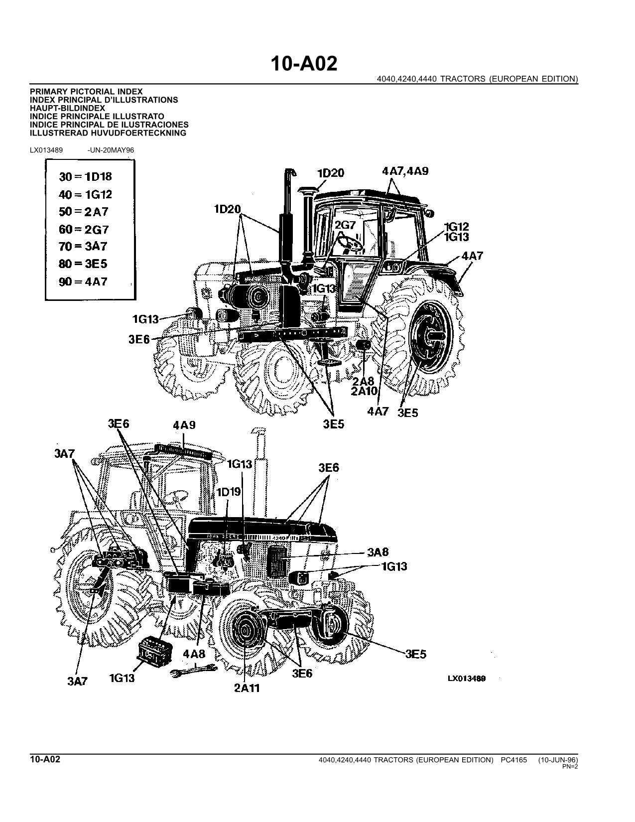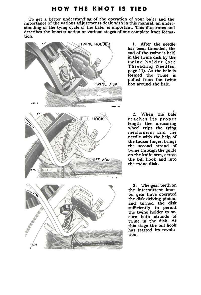
Effective maintenance of farm equipment relies on understanding the inner workings of its various components. A well-detailed visual reference is essential for identifying and repairing specific sections of your machinery. Such resources help operators perform routine inspections, troubleshoot issues, and replace damaged parts, ensuring optimal performance over time.
By referring to detailed breakdowns of these mechanical systems, users can gain a deeper insight into the structure and function of key elements. Familiarity with these components allows for more efficient repairs, reducing downtime and enhancing productivity in the field.
For anyone looking to extend the lifespan of their equipment, it is crucial to have access to accurate schematics. Understanding how individual parts fit together ensures that maintenance tasks are carried out with precision and care.
Understanding the Agricultural Machine Components

Farm equipment operates through a network of interlinked systems, each serving a specific function to ensure smooth operation. The efficiency of these machines depends on the seamless integration of mechanical elements, from the most basic to the most complex parts. A clear understanding of each component’s role within the machine allows operators to maintain and repair their equipment more effectively.
The core elements of this machinery include drive systems, cutting mechanisms, and material handling parts, which work in harmony to perform tasks efficiently. Identifying these components and knowing how they interact with each other is key to troubleshooting and maintaining machine health over time. By closely studying these features, users can pinpoint areas that may require attention or adjustment.
In-depth knowledge of the machine’s components not only aids in day-to-day operations but also enhances long-term reliability. Recognizing wear patterns, understanding when to replace specific elements, and having the right tools for repairs can prevent costly breakdowns and extend the lifespan of the equipment.
How to Read the Components Breakdown Effectively
To maintain and repair farm machinery, understanding the detailed schematics is essential. These visual guides provide a clear representation of how different elements within the machine fit together and function. Interpreting these diagrams correctly ensures that repairs are performed accurately and efficiently, preventing unnecessary mistakes and downtime.
Start by identifying the main sections of the diagram. Each segment typically highlights a specific area or system within the machine, such as the drive mechanism or the material handling system. Pay attention to the labels and numbers that correspond to individual components, as they allow you to match them with the actual parts in your equipment.
Take note of the various lines and symbols used in the diagram. Solid lines often represent structural connections, while dashed or dotted lines indicate moving parts or electrical connections. Understanding these symbols is crucial for correctly interpreting how components interact with one another.
Lastly, cross-reference the diagram with the machine’s manual to ensure the accuracy of the visual representation. Familiarity with both the schematic and the physical layout of the equipment will enhance your ability to diagnose issues and perform repairs effectively.
Common Issues with Agricultural Machine Components

Like all complex machinery, farm equipment is prone to a variety of mechanical issues over time. Regular usage, harsh field conditions, and lack of proper maintenance can contribute to wear and tear, resulting in problems with different sections of the machine. Understanding these common issues can help prevent breakdowns and ensure smooth operation.
Some of the frequent problems that arise include:
- Drive system malfunctions: Worn-out belts, chains, or gears can cause a loss of power or inefficient movement.
- Misalignment of moving parts: Over time, components can shift out of alignment, leading to unnecessary friction and potential damage to connected elements.
- Clogging in material handling systems: The accumulation of debris or overuse can block pathways, affecting the machine’s ability to process material efficiently.
- Hydraulic system failures: Leaks or faulty valves can disrupt the functionality of hydraulic-driven parts, compromising performance.
- Wear on cutting or compression elements: Dull blades or damaged rollers can lead to poor processing quality or machine stoppage.
Regularly checking for these issues and addressing them promptly is key to maintaining equipment efficiency and extending its lifespan. By familiarizing yourself with the typical problems that arise, you can act quickly and avoid more serious damage in the future.