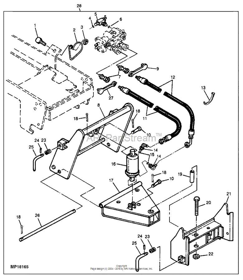
Maintaining and repairing machinery requires a clear understanding of its structure and individual elements. A visual reference to the various components is invaluable for both professionals and enthusiasts. Whether you’re performing routine checks or more advanced repairs, knowing where each part fits and how it functions is crucial for efficient operation.
By consulting detailed illustrations, you can easily identify key elements, reducing the time spent troubleshooting and ensuring that everything works as intended. These detailed guides help you make informed decisions when replacing or servicing any part.
Familiarity with these visual aids will not only improve your repair skills but also enhance your ability to keep your equipment running smoothly. Understanding how to interpret these charts is an essential step in ensuring the longevity and reliability of your machinery.
Understanding John Deere 425 Diagrams
For anyone involved in machinery maintenance or repair, visual charts are indispensable tools that offer clear representations of complex systems. These detailed illustrations allow users to pinpoint specific components within the machinery, helping them make precise adjustments or replacements with ease. Such references simplify the process of understanding how each individual part contributes to the overall functionality of the equipment.
Having a comprehensive guide to refer to when working on your machine can significantly improve efficiency. By carefully examining these visual representations, you can identify areas that may need attention, ensuring smooth operation. These visuals not only aid in troubleshooting but also enhance the speed of maintenance tasks.
Being able to read and interpret such charts is a key skill for anyone who wants to ensure optimal performance and longevity of their equipment. With proper knowledge of how parts are structured and interrelated, you can avoid costly mistakes and keep your machinery running at its best.
Locating Key Parts for Maintenance
Effective maintenance starts with knowing where each critical component is located within the machine. Identifying key elements before beginning any repair or service task helps streamline the process and prevents unnecessary disassembly. A well-organized guide to the main sections of the equipment ensures that technicians can quickly address issues without wasting time searching for the parts in question.
Identifying Essential Components
Some parts play more crucial roles than others in the smooth operation of machinery. By understanding which components require regular attention, you can prioritize your efforts during inspections and ensure everything is functioning properly. Key components such as the engine, transmission, and control systems are typically highlighted in maintenance manuals, allowing easy identification.
Using Visual Aids to Find Parts
Visual aids offer a convenient way to locate and identify parts that might otherwise be difficult to access or distinguish. These charts and diagrams provide a straightforward visual map, making it easier for anyone performing maintenance to spot the exact parts that need attention. Using these guides can save significant time and reduce the risk of overlooking critical components during service.
How to Read John Deere Diagrams

Interpreting visual guides effectively is essential for anyone performing equipment maintenance or repairs. These charts offer valuable information on the layout and connections between different components. Understanding how to read these visual references ensures that tasks are completed accurately and efficiently, preventing unnecessary errors.
Understanding Symbols and Labels
Each visual guide includes specific symbols and labels that represent various components and functions. Familiarizing yourself with these icons is crucial as they will help you quickly identify each part’s role in the system. Some parts may be highlighted with different colors or patterns, providing additional context for their function or importance within the overall setup.
Following the Sequence of Assembly
Many charts display a step-by-step sequence for assembly or disassembly. By following this logical progression, you can easily understand the flow of the system and locate each part in relation to others. Staying mindful of the order in which parts are connected helps ensure that everything is correctly aligned and functioning as intended.