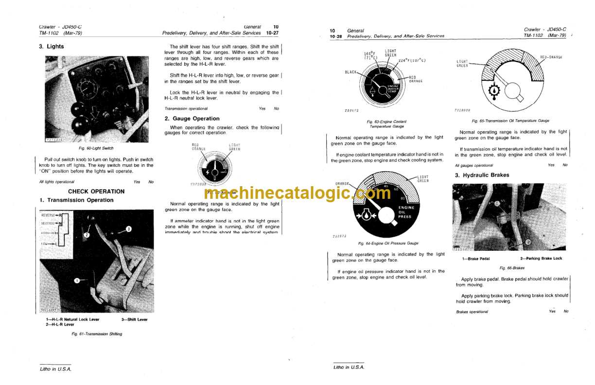
When working with heavy machinery, having access to accurate and detailed schematics is essential for ensuring smooth operation and efficient maintenance. These technical drawings help operators and mechanics quickly identify components, troubleshoot issues, and make necessary repairs. A comprehensive visual guide offers clarity and allows users to understand the layout of the machine, pinpointing parts and their connections for easier handling.
Using these technical charts, owners can enhance the lifespan of their equipment and reduce downtime caused by unnecessary repairs. Whether you are performing routine maintenance or addressing a specific malfunction, having a reliable reference for machine assembly is crucial. Understanding how each piece fits together provides the confidence needed to tackle repairs with precision.
Understanding the John Deere 450C Diagram
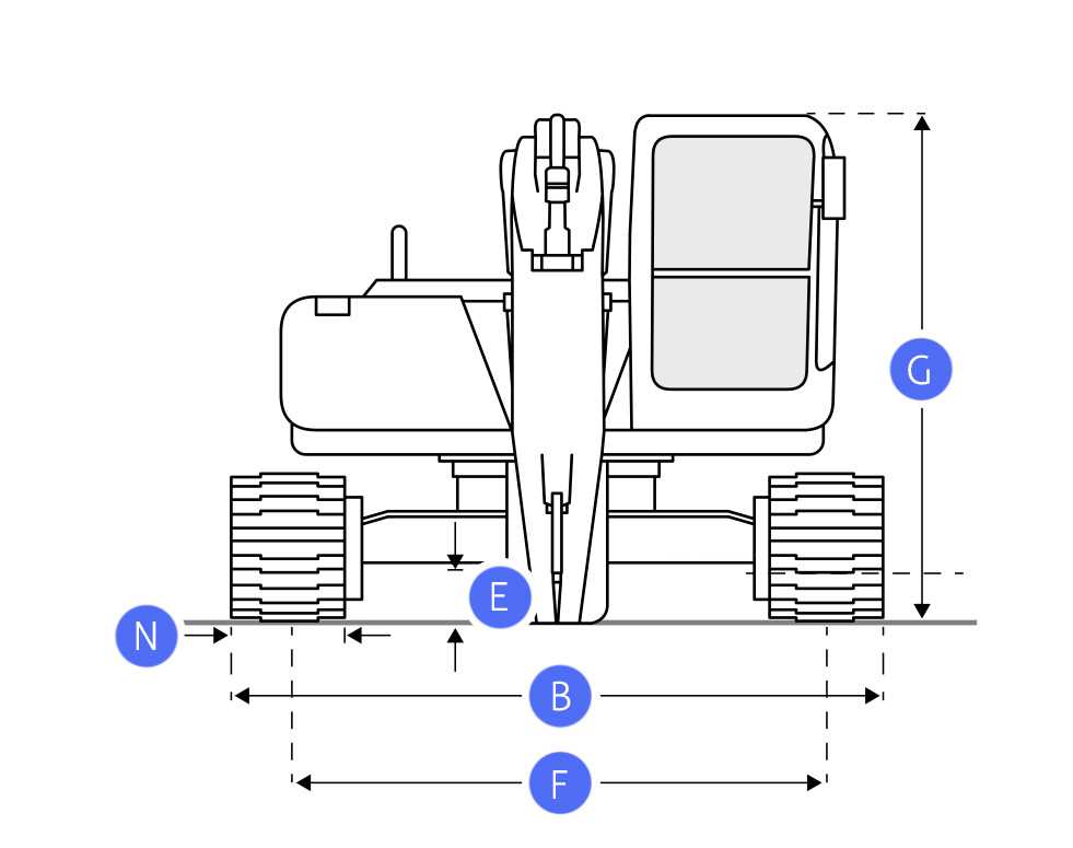
Detailed technical illustrations are an invaluable tool when it comes to maintaining and repairing complex machinery. These visuals provide a clear, organized view of the equipment, enabling users to identify components, their functions, and how they connect with one another. By understanding the layout and structure shown in these references, mechanics can work more efficiently and minimize mistakes during repairs or part replacements.
How Technical Schematics Simplify Repairs
These visuals break down the machine into individual sections, making it easier to focus on specific areas that require attention. By isolating components and showing their relationships, these guides help identify the root cause of problems, speeding up troubleshooting and improving the accuracy of repairs. Whether it’s an engine, hydraulic system, or electrical circuit, these clear drawings ensure that every part is understood and properly handled.
Key Features of the Visual Guide
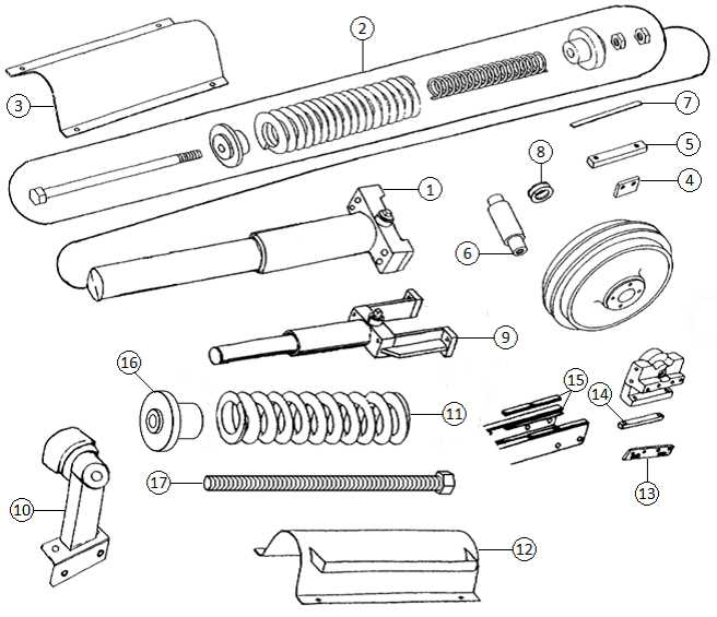
One of the primary benefits of these illustrations is their level of detail. They often include labels and annotations that explain the function of each part, its location, and how it interacts with other components. This clarity reduces the chances of missing critical steps during maintenance, helping users stay on track and avoid unnecessary disassembly. These guides are designed to make repairs more accessible and reduce downtime, ultimately improving the overall efficiency of the equipment.
How to Use the 450C Parts Diagram
Using technical illustrations effectively requires a methodical approach. The first step is to familiarize yourself with the layout of the machine as depicted in the guide. Understanding how the parts are organized on the chart helps you quickly locate the specific components you need to work on. These visual references are meant to serve as a roadmap, simplifying complex tasks by clearly identifying each section and its corresponding pieces.
To make the most out of these visual aids, start by identifying the area that needs attention. Once you’ve pinpointed the relevant section, cross-reference the labeled components with the machine in front of you. This allows you to confirm the parts’ locations and ensures you’re working on the correct section. Additionally, keep in mind that these guides often include important details about part numbers and compatibility, which can be crucial when ordering replacements or making adjustments.
Common Repairs with John Deere 450C Parts
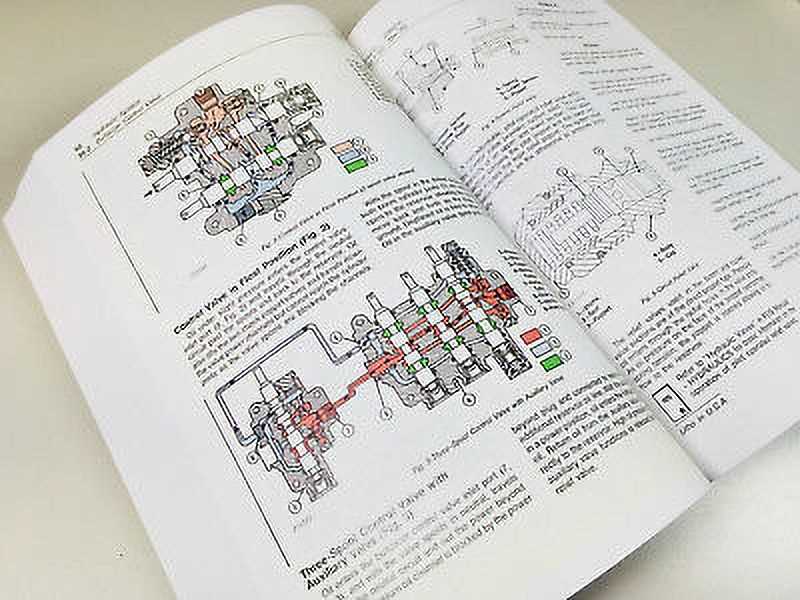
Heavy machinery often requires routine maintenance and occasional repairs to ensure optimal performance. Some of the most common issues involve the engine, hydraulic system, and transmission components. Identifying and addressing these problems early can prevent larger, costlier repairs down the road. Properly understanding the function and location of each part makes troubleshooting simpler and more efficient, reducing downtime and extending the lifespan of the equipment.
Engine Overhaul is a frequent repair need in machinery. Over time, components such as pistons, valves, and filters wear out, which can lead to reduced efficiency or engine failure. By referencing the schematics, users can pinpoint the exact components that require attention, facilitating faster repairs.
Hydraulic System Failures are another common issue, often caused by leaks or damage to hoses and cylinders. These problems can disrupt the machine’s ability to perform heavy lifting or operate certain functions. A detailed visual guide helps identify the specific hydraulic components, enabling quick identification of damaged or worn parts.
Transmission Repairs may be necessary when the machine experiences issues with shifting or loss of power. In such cases, identifying the exact transmission components and their connections is critical to making a successful repair. Understanding the visual layout ensures that mechanics can assess the issue quickly and address it with minimal effort.