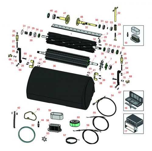
Efficient maintenance of machinery requires a clear understanding of its internal components and their interconnections. A visual representation can be an invaluable tool for identifying specific parts and their functions. This guide will explore how to make use of detailed illustrations to enhance repair and upkeep processes.
By utilizing a comprehensive visual map, users can quickly locate the components that need attention, making maintenance tasks faster and more accurate. Whether you’re troubleshooting or performing routine servicing, such diagrams offer clear insights into the assembly and disassembly of the machine.
Mastering these illustrations ensures that you can maintain your equipment’s performance at peak levels. With the right knowledge, any user can confidently address issues and extend the lifespan of their machinery.
Understanding Key Components of the Equipment
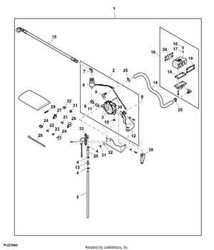
To maintain and repair heavy machinery, it’s crucial to have a clear understanding of the internal mechanisms that allow it to function. Identifying the individual elements and knowing their roles can simplify the process of troubleshooting and servicing. This section will explore the primary components that make up the system, offering insights into their placement and purpose.
Major Elements and Their Functions
Each machine is built with a variety of essential components, each contributing to its overall operation. From drive mechanisms to control systems, understanding how these parts interact is fundamental for effective maintenance. Recognizing the role of each part helps in preventing unnecessary damage and ensures that the machine performs optimally over time.
Common Areas of Wear and Tear
Certain components are more prone to wear, often requiring more frequent inspections and replacements. These parts are typically exposed to high stress and operational strain. Knowing which areas are more susceptible to damage allows for proactive maintenance, reducing downtime and improving the longevity of the equipment.
Identifying Key Parts in the Diagram
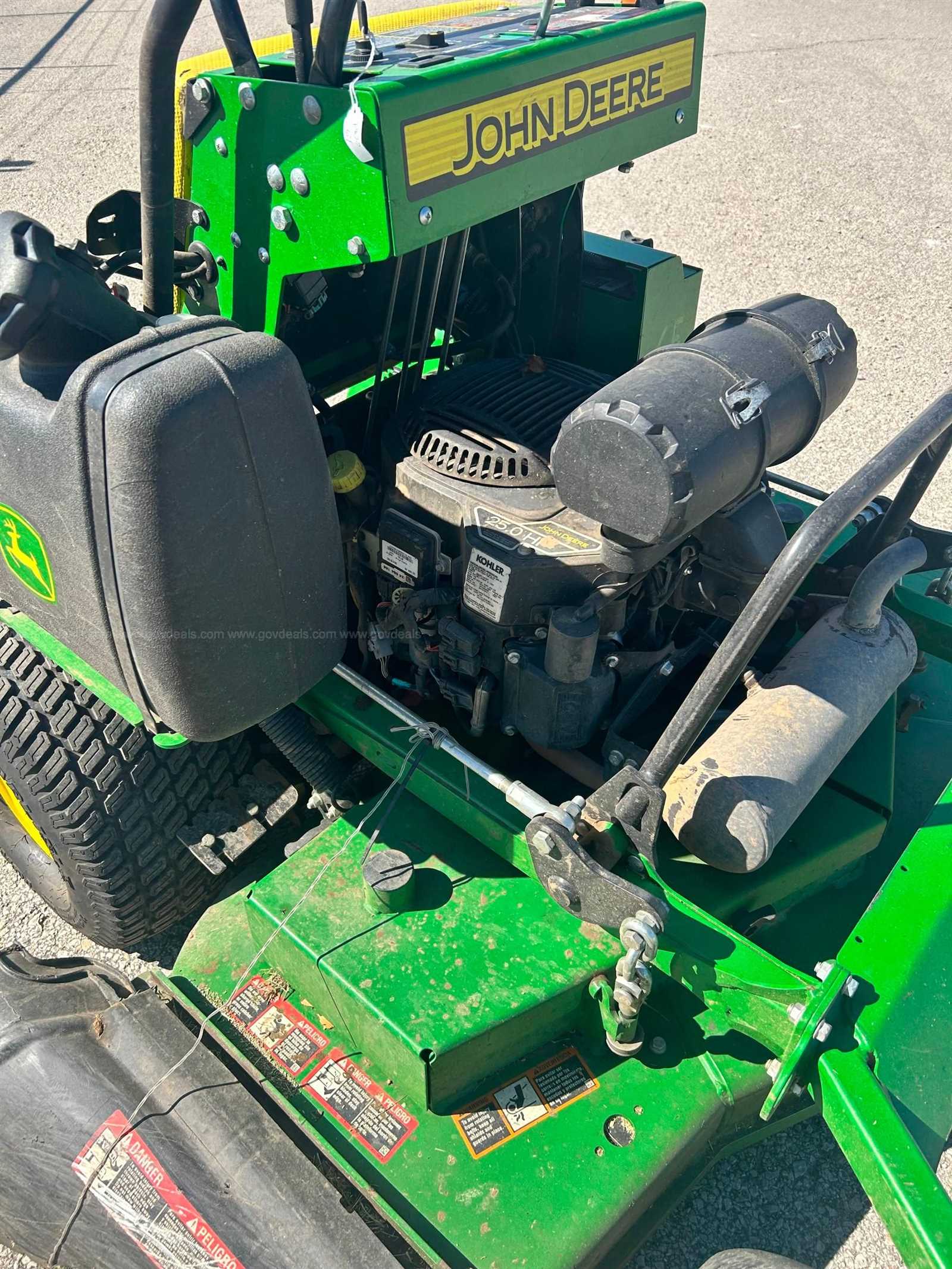
Understanding the layout of essential components is crucial for effective maintenance and repair. Every system or machinery has specific elements that ensure smooth operation. By recognizing and learning how to locate these vital pieces, one can prevent common issues and improve the overall performance. This section helps in identifying the most important elements in a visual representation of the equipment, offering insights into their roles and functions.
Main Assembly Components
The core structures that support the entire mechanism are highlighted in the schematic. These are usually the primary elements that allow other parts to function efficiently. Familiarity with these components provides a foundation for troubleshooting and replacing worn-out pieces. Their proper identification leads to quicker diagnostics, ensuring the equipment remains operational for longer periods.
Other parts in the layout serve specific roles in the performance of the machine. These subsystems are designed to perform tasks such as power transmission, control, and safety. Recognizing how each subsystem is interconnected with the main body aids in understanding the machinery’s overall functionality, ultimately enhancing repair accuracy and minimizing downtime.
How to Use the John Deere 652R Diagram
Mastering the representation of key components is essential for efficient repairs and maintenance. These visual tools help users navigate the intricate structure of the machine, highlighting crucial sections that require attention. By understanding how to read and interpret these visual layouts, users can streamline their troubleshooting process, perform precise repairs, and extend the lifespan of the equipment.
Reading the Layout
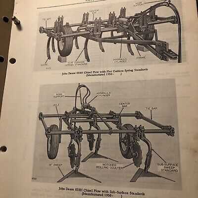
Begin by familiarizing yourself with the overall structure. The schematic is organized into distinct sections, each corresponding to a specific system within the machine. Start with the largest sections, then narrow down to individual components. Understanding the relationships between these parts ensures an accurate approach when diagnosing issues. Pay attention to the labels and any visual cues that indicate connections or potential problem areas.
Utilizing for Troubleshooting
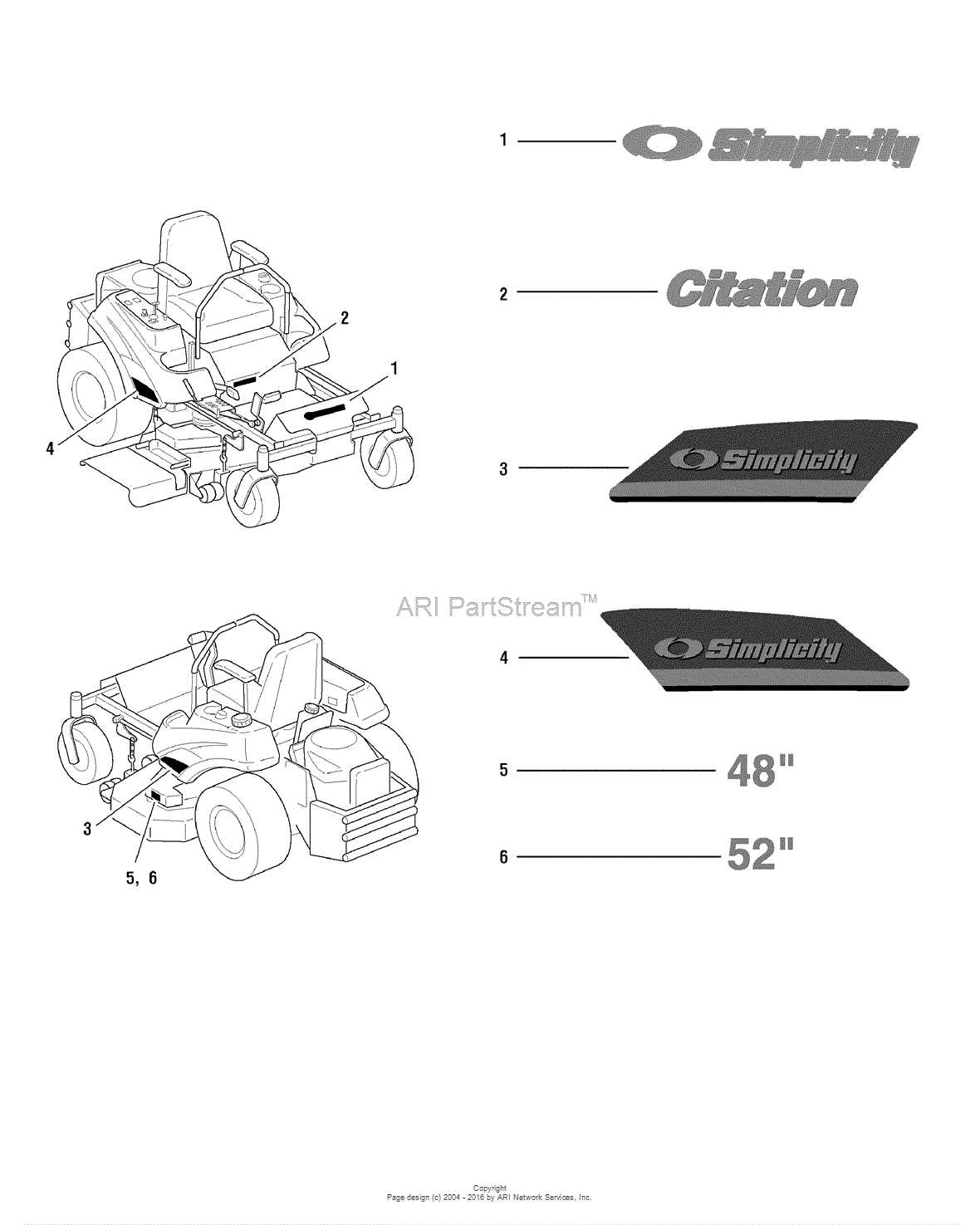
For effective troubleshooting, identify the system that aligns with the issue you’re facing. By cross-referencing the visual guide with the symptoms of the malfunction, pinpoint the most likely components to check. Check for wear, misalignment, or other signs of damage based on the diagram’s pointers. This targeted approach minimizes unnecessary repairs and ensures that only the most critical areas are addressed.