Efficient farming equipment requires regular maintenance and precise knowledge of its components. A clear understanding of the machine’s construction allows for quicker repairs and optimal performance. When managing advanced agricultural tools, recognizing the individual elements that make up the system is essential to ensuring long-term functionality.
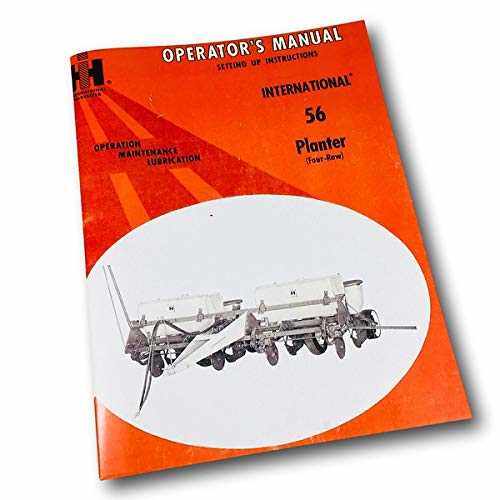
In this guide, we will explore the structure of a four-row planting system and help you identify the key elements that contribute to its operation. Familiarizing yourself with the intricate details of this equipment will enable you to improve your maintenance practices and troubleshoot potential issues before they become major problems.
Proper care and attention to every component can drastically reduce downtime and extend the lifespan of your machinery. By following this comprehensive approach, farmers can maintain their equipment with confidence, ensuring that each part contributes to the overall efficiency of the planting process.
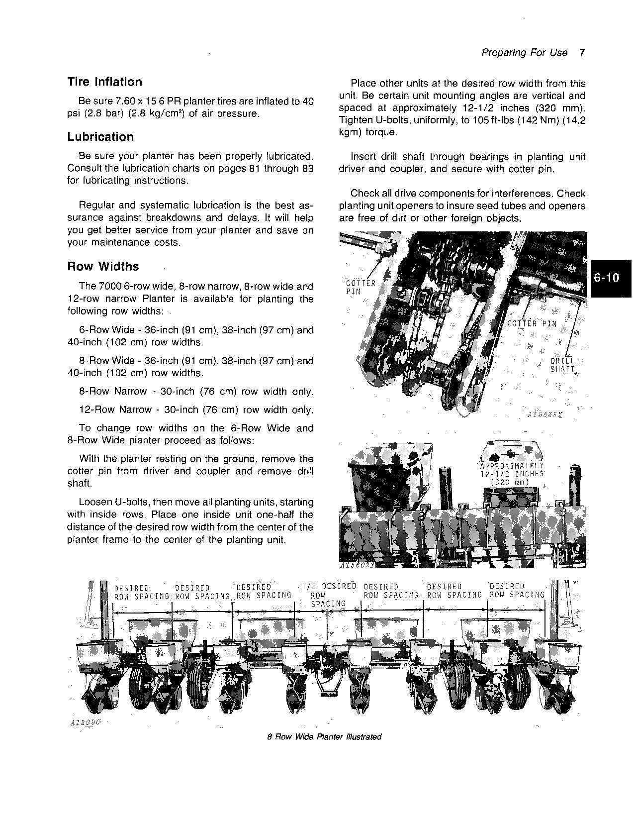
Understanding the John Deere 7000 Planter
Efficient farming requires equipment that can handle the demands of large-scale cultivation. The system in question is designed to plant crops quickly and accurately, ensuring that each seed is placed in the ideal position for optimal growth. This tool is a vital part of modern farming, especially when it comes to ensuring high yields and precision during the planting phase.
To truly understand the mechanics of this system, it’s essential to look at the individual components that make up the machinery. Each part works in harmony to perform specific tasks, from seed placement to soil management, making it a sophisticated tool for any agricultural operation.
Core Features of the Equipment
This machine is equipped with several key features that enhance its efficiency. The components are engineered to work seamlessly together, ensuring that every planting cycle is consistent. From the seed metering system to the ground engagement tools, every part plays a role in maximizing productivity and minimizing errors.
Key Benefits of Proper Maintenance
Maintaining the equipment is essential for preserving its performance over time. Regular upkeep ensures that each part functions at its best, reducing wear and tear, and avoiding costly repairs. Understanding how each element interacts within the system allows farmers to diagnose issues early and maintain optimal operation throughout the planting season.
Key Components of the 4 Row Planter

Every piece of agricultural equipment is made up of a series of essential components that work together to achieve efficiency and precision in the field. Understanding the individual functions of these parts allows operators to maintain, troubleshoot, and operate the machinery with ease. In this section, we will explore the primary elements that make up a four-unit planting system and how each one contributes to the overall performance of the equipment.
Seed Metering and Distribution System
One of the most crucial aspects of the system is the seed metering mechanism. This component ensures that each seed is dispensed accurately, placed at the correct depth, and spaced evenly to promote healthy plant growth. The consistency of the seed delivery directly impacts the efficiency of the planting process and the success of the crop yield.
Soil Engagement Tools and Depth Control
Proper soil engagement is vital for preparing the ground for seed placement. The tools that engage the soil, such as the closing wheels and depth control systems, ensure that the seed is positioned at the optimal depth for germination. These components also help manage soil compaction, promoting proper root growth and ensuring that the seeds are well-protected after planting.
How to Read the Parts Diagram
Understanding how to interpret technical drawings is a crucial skill for maintaining complex agricultural machinery. These visual guides provide a detailed breakdown of every component, showing their placement and how they interact with one another. By learning how to read these illustrations, operators and technicians can easily identify parts, understand their functions, and determine how to properly assemble or repair them when needed.
Identifying Components and Their Functions
Each component is represented by a specific symbol or shape in the drawing. Labels and numbers often accompany these symbols, making it easier to reference parts when ordering replacements or conducting repairs. Understanding the key features and their role within the system allows for a more efficient workflow and helps prevent errors during maintenance tasks.
Interpreting Connections and Assembly Instructions
Along with individual parts, the diagram often shows how various components are connected or assembled. Arrows or lines indicate the flow of the system, guiding users to understand how different elements interact with one another. This can be particularly helpful when troubleshooting issues, as it allows users to trace the root cause of a problem through the system’s layout.