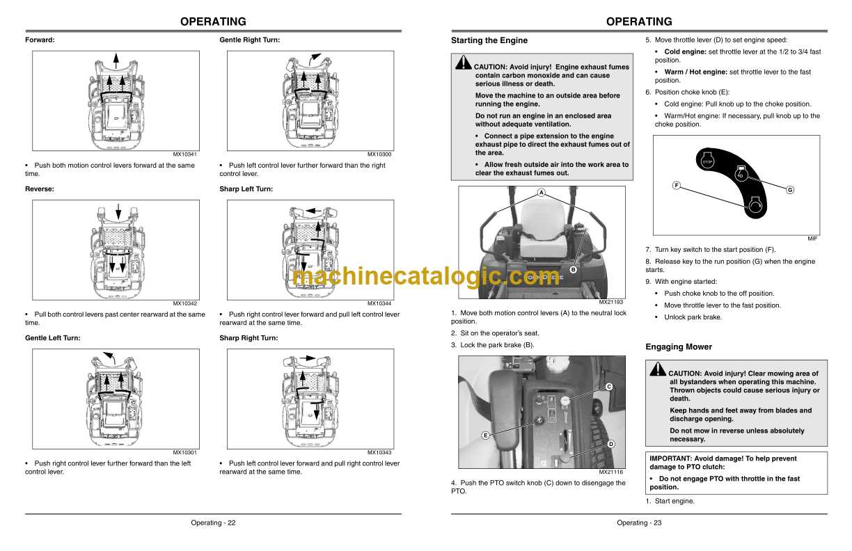
When it comes to maintaining and repairing a lawn care machine, understanding its internal structure is essential. Knowing how various elements fit together ensures efficient performance and long-lasting operation. For enthusiasts and professionals alike, having a clear reference for each component is a crucial step in both troubleshooting and upgrading machinery.
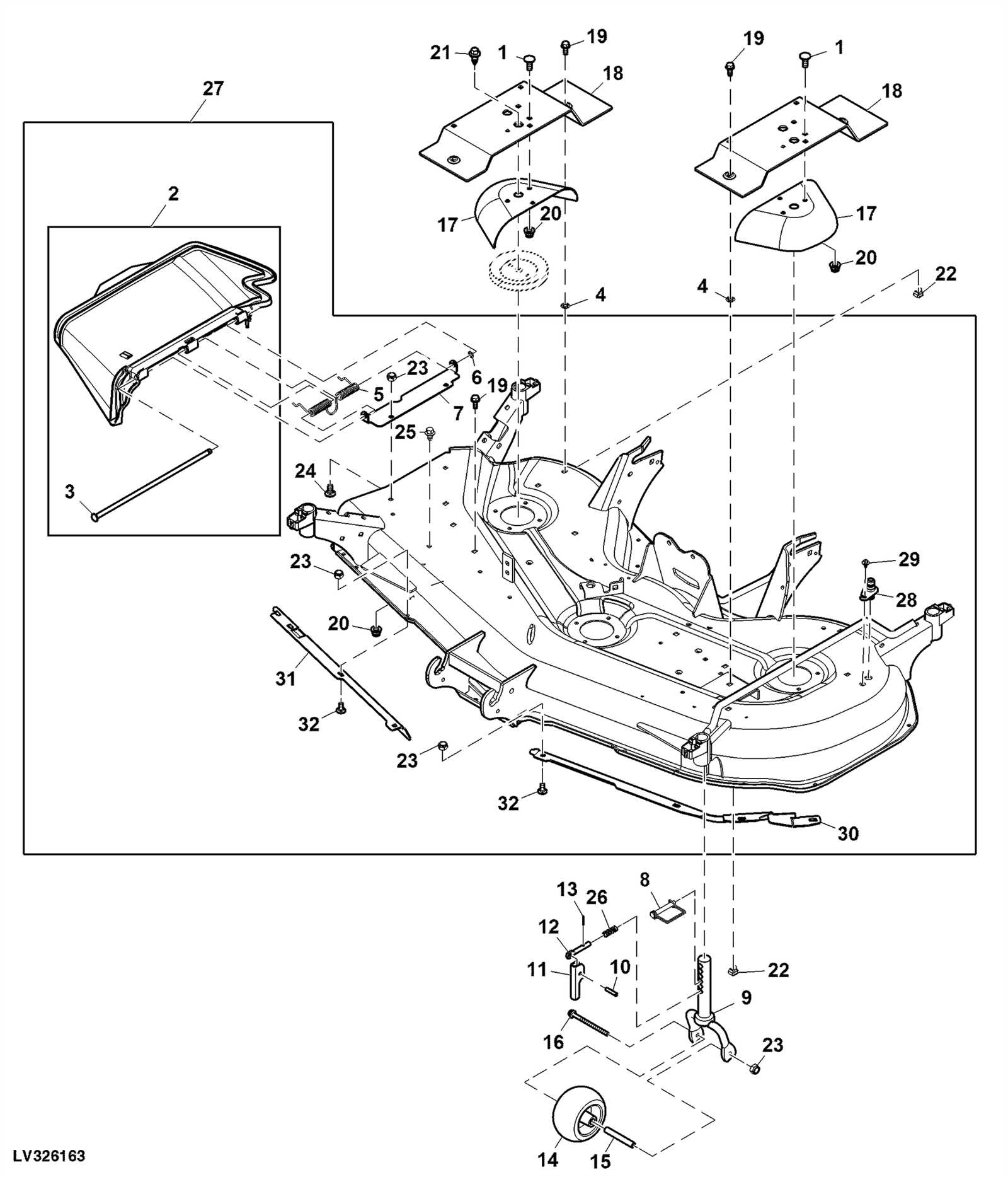
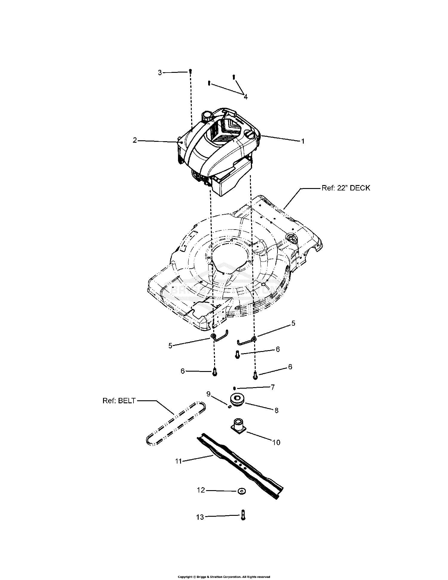
Detailed schematics provide users with the opportunity to identify every essential part, from the engine to the cutting mechanism. These visual aids help users navigate complex systems, making it easier to spot potential issues or areas for improvement. Whether you’re replacing worn-out components or conducting regular maintenance, such references serve as an invaluable resource.
In this guide, we will explore how to utilize these visual tools effectively to understand machine construction, ensuring that every part is in optimal working condition. A well-maintained machine leads to better results and fewer interruptions, allowing users to tackle tasks efficiently.
Understanding the John Deere 737 Diagram
To maintain and repair any mechanical equipment effectively, a clear understanding of its design is essential. A visual reference showing how each individual element interacts allows for a more straightforward approach to fixing and optimizing performance. This guide provides insights into how these visual tools can be utilized to ensure that everything is in working order.
By examining a detailed layout, users can easily identify the relationship between the different components, whether it’s for engine maintenance, structural integrity, or other operational aspects. A comprehensive view helps in recognizing potential issues early on, allowing for targeted solutions that can extend the lifespan of the machinery.
Utilizing such a reference is not only beneficial for repairs but also for improving machine efficiency. Understanding each part’s function within the whole system empowers users to make informed decisions when it comes to upgrades, troubleshooting, and maintenance procedures. This section aims to simplify that process by breaking down the complexities of the mechanical layout into manageable insights.
Key Components of John Deere 737

Understanding the essential elements of a lawn care machine is crucial for proper maintenance and efficient operation. Each component plays a specific role in ensuring smooth functionality and longevity. This section highlights the core parts that make up the machinery, from the engine to the cutting system, offering insights into their functions and importance.
Engine and Power System
The heart of any mechanical device is its engine, and this is no exception. The power system is responsible for driving all other components, providing the necessary energy for operation. A well-maintained engine ensures optimal performance, reducing wear and tear on other parts. Regular checks and proper fuel management are key to preventing issues with this critical component.
Transmission and Drive Mechanism

The transmission system transfers power from the engine to the wheels, enabling movement. The drive mechanism, including belts and pulleys, ensures that the machine can move and function effectively. Regular maintenance, such as adjusting tension or replacing worn-out belts, is essential for preventing mechanical failure and maintaining smooth operation.
Each component within the machine works in harmony to provide optimal performance. Recognizing how these parts interact and ensuring their proper care can significantly improve the reliability and lifespan of the equipment. Whether you’re looking to troubleshoot or enhance functionality, understanding these key elements is the first step in the process.
How to Use the Parts Diagram
Utilizing a schematic reference is a valuable tool when working on mechanical equipment. It provides a clear visual representation of the various components and how they interact within the system. By carefully analyzing this reference, users can identify individual parts, understand their functions, and troubleshoot effectively.
To make the most of this resource, start by familiarizing yourself with the layout. Focus on the organization of parts, ensuring you understand where each element is located within the structure. Take note of any labels or part numbers, as they can guide you to specific replacements or maintenance procedures.
When addressing an issue, cross-reference the malfunctioning component with its corresponding part on the visual guide. This process helps to pinpoint the root cause quickly, saving time during repairs. Additionally, this visual tool aids in understanding how adjustments or upgrades to one part might affect the overall system.