For any machinery owner, understanding the internal mechanisms of the equipment is crucial for long-term reliability and performance. When it comes to agricultural vehicles, having a clear understanding of each individual component can simplify both maintenance and repairs. Accurate identification of each element ensures that proper actions are taken, preventing unnecessary downtime and costly mistakes.
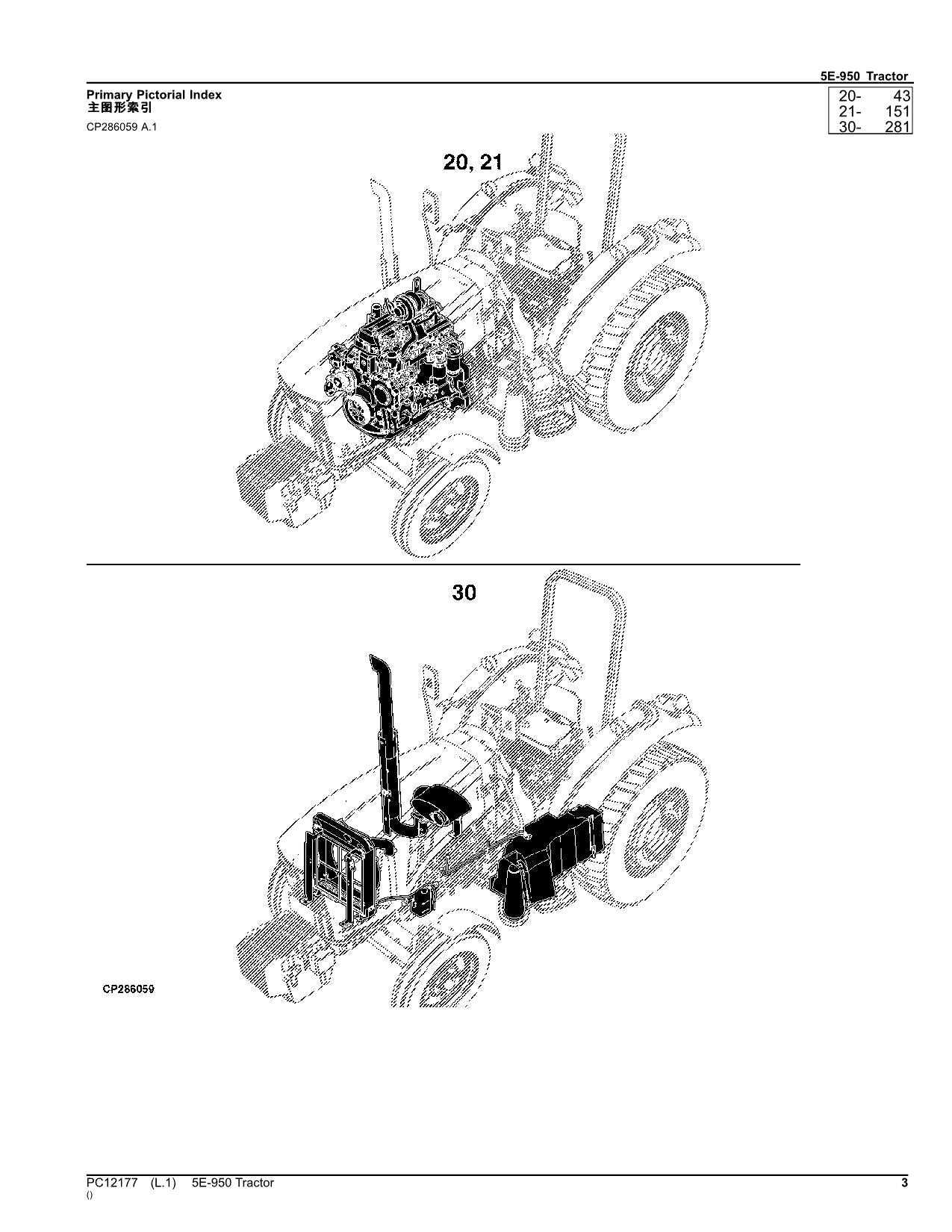
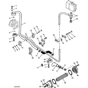
Detailed visual guides are invaluable tools that assist in this process. These resources provide clear illustrations that break down complex systems into understandable segments, helping operators navigate repairs or replacements with confidence. Such visuals are essential for both experienced technicians and those new to maintaining heavy machinery.
Incorporating comprehensive charts into the repair process enhances overall operational efficiency, making it easier to identify wear and tear. This proactive approach leads to a more productive use of the machinery, extending its lifespan while avoiding disruptions during crucial farming seasons.
Understanding the Tractor Components
Proper maintenance of heavy machinery starts with a clear comprehension of its internal structure. Every individual component plays a vital role in ensuring smooth operation, from the engine to the transmission system. A detailed understanding of these elements allows for more efficient troubleshooting and repair, reducing downtime and keeping operations running smoothly.
Each section of the vehicle, whether it’s the powertrain or the hydraulic system, is interconnected. Identifying how these sections work together is essential for diagnosing potential issues and addressing them before they escalate. When operators are familiar with the structure of their equipment, they are better equipped to make informed decisions about repairs and upgrades.
Maintenance becomes significantly more manageable when each part is recognized for its unique function. Knowing the specifics of each mechanism helps operators maintain the vehicle’s performance and avoid costly replacements. This knowledge also provides a foundation for optimizing the machinery’s efficiency in the long run, ensuring it meets the demands of its intended tasks.
Identifying Key Parts for Repair and Replacement
When maintaining heavy machinery, recognizing which components are most vulnerable to wear is essential for ensuring continued performance. Some parts are more prone to damage due to constant use or environmental factors, making timely identification crucial. Understanding these parts allows for effective troubleshooting and proactive maintenance, avoiding costly and unexpected breakdowns.
Components Most Prone to Wear

Mechanical and moving elements like belts, gears, and filters are commonly subjected to wear and tear. These components require regular inspection to ensure they are functioning optimally. Ignoring minor damage in these areas can lead to major system failures, which could halt operations for extended periods.
Effective Replacement Strategies
Once key parts have been identified as worn or malfunctioning, knowing when and how to replace them is vital for the machine’s longevity. Replacing components at the right time, before they fully degrade, minimizes downtime and prevents further damage to the overall system. Regularly updating essential elements ensures that the vehicle remains in top operating condition and reduces the need for more extensive repairs.
Step-by-Step Guide to Tractor Assembly
Assembling a complex agricultural vehicle involves several critical steps to ensure all components are securely installed and function as intended. Each phase of the assembly process should be carefully followed to avoid errors that could compromise the machine’s performance. By understanding the order of assembly and the purpose of each section, technicians can perform the task more efficiently and accurately.
Initial Assembly Steps
The first stage involves preparing the frame and basic mechanical systems. This includes assembling the chassis, engine mounts, and ensuring the transmission system is properly aligned. Ensuring that each part is securely fastened is crucial for long-term durability and smooth operation.
Final Assembly and Adjustments
After the core systems are in place, attention turns to the finer details such as hydraulic connections, electrical systems, and attachments. Calibration and final adjustments are necessary to ensure the vehicle operates at its optimal level. Proper testing during this stage helps identify any potential issues before the machinery is put into full service.
| Step | Task | Purpose |
|---|---|---|
| 1 | Frame and Chassis Assembly | Ensure structural integrity |
| 2 | Transmission Installation | Ensure proper gear functioning |
| 3 | Hydraulic Connections | Enable fluid power for movement |
| 4 | Electrical System Setup | Power various systems |
| 5 | Attachment Installation | Complete operational capability |
Visualizing Assembly with Detailed Diagrams

Clear and precise illustrations are essential for understanding the assembly process of complex machinery. These visual guides break down intricate systems into manageable sections, making it easier to follow each step and avoid errors. By using diagrams, technicians can ensure that all components are positioned correctly, reducing the risk of assembly mistakes and improving overall efficiency.
Benefits of Visual Guides
Using detailed visuals to guide assembly brings several advantages:
- Clarity: They provide a clear understanding of each part’s placement and connection.
- Precision: Accurate positioning of components ensures proper function and longevity.
- Efficiency: Helps save time by allowing technicians to focus on tasks without uncertainty.
Key Steps for Assembly Visualization
To effectively utilize visual aids during assembly, technicians should follow these key steps:
- Identify the section of the machinery to be assembled.
- Review the corresponding diagram to understand the component layout.
- Verify the components against the diagram to ensure all necessary parts are available.
- Follow the diagram’s guidance to assemble each part step by step, ensuring correct alignment.
Maintaining Efficiency with Accurate Part Identification
For machinery to function optimally, it is essential to quickly and accurately identify each component. When parts are correctly recognized and categorized, it becomes much easier to address issues, perform maintenance, and ensure the equipment operates at peak efficiency. The ability to swiftly pinpoint a malfunctioning or worn part helps prevent unnecessary delays and prolongs the lifespan of the machine.
Accurate identification also reduces the likelihood of ordering incorrect replacements, saving both time and resources. By understanding the specifications and functions of each component, technicians can streamline repairs, making the entire process more cost-effective and less time-consuming. This approach ultimately contributes to smoother operations and improved productivity.
Moreover, knowing the precise role of every element ensures that replacements and repairs are performed correctly. A clear understanding of each part’s function allows technicians to avoid errors that could compromise the machine’s performance. Proper identification not only supports troubleshooting but also optimizes overall machinery output, ensuring that the vehicle runs as efficiently as possible throughout its service life.