For those looking to maintain or repair their machinery, understanding the internal structure is crucial. A clear breakdown of each element helps to identify issues quickly and ensures efficient servicing. Proper knowledge of how individual parts fit together can significantly reduce repair time and improve overall performance.
Visual representations of these structures provide a detailed overview that makes identifying the right components easier. These references serve as invaluable tools for technicians and operators who need to troubleshoot problems or perform maintenance tasks.
By familiarizing yourself with these schematics, you can avoid costly errors, streamline repairs, and ensure that the equipment continues to run smoothly for years to come. Understanding the relationship between parts also enhances your ability to spot wear and tear before it becomes a bigger issue.
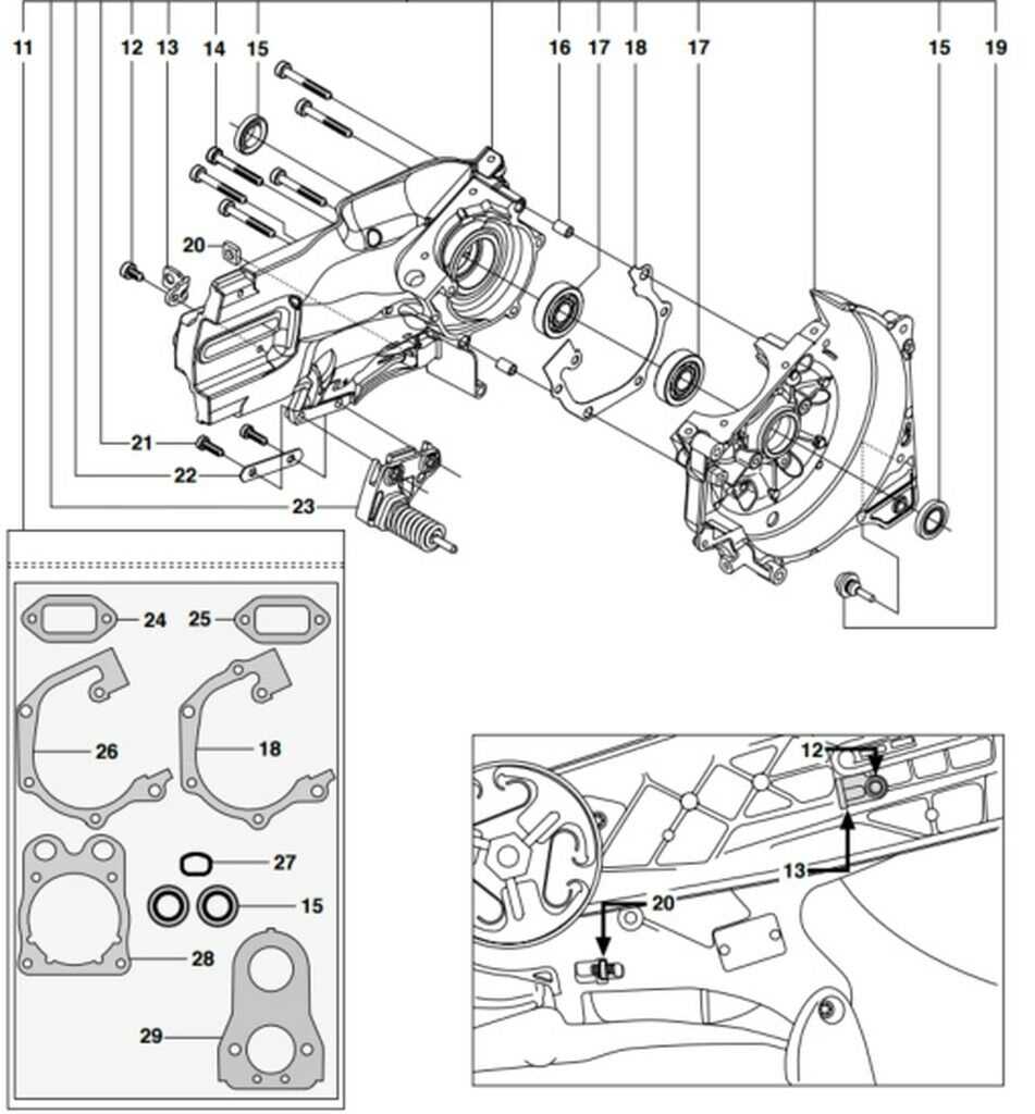
Understanding the K770 Parts Layout

Having a clear understanding of the layout of machine components is essential for effective maintenance and repair. A comprehensive map of the internal structure helps users quickly identify where each part fits and how they interact. This knowledge can greatly improve the efficiency of any service work by allowing technicians to address issues more accurately and quickly.
Each element within the equipment is positioned in a specific arrangement that contributes to the overall performance. Recognizing the exact role of each piece is crucial for troubleshooting or upgrading. A visual guide allows users to pinpoint areas that require attention, whether it’s a minor adjustment or a major replacement.
Familiarity with this layout not only speeds up repairs but also prevents unnecessary disassembly of unrelated sections. By following a structured approach based on the layout, you can ensure that maintenance tasks are carried out with minimal disruption, improving the lifespan of the machinery.
How to Identify K770 Components
Properly identifying the individual elements of machinery is a key part of effective maintenance. Recognizing each component allows for quick diagnosis of problems and precise repairs. The identification process involves understanding the function of each piece and knowing where it fits within the overall system.
Step-by-Step Identification Process
Start by referencing a detailed guide that highlights each element. Focus on the shape, size, and unique features of the components. This will help you distinguish between similar-looking pieces and ensure that the right part is being addressed for a specific issue.
Utilizing Markings and Labels

Many components have clear markings or labels that can assist in identification. These could include part numbers, serial numbers, or brand identifiers. Being familiar with these labels allows for quick matching to manufacturer specifications and ensures that replacements are accurate.
Benefits of Using a Parts Diagram

Utilizing a visual reference for machine components offers significant advantages when it comes to both repair and maintenance. These guides help to clearly outline the structure, making it easier to understand how each element fits and functions within the system. This clarity enhances troubleshooting efficiency and reduces the time spent locating issues.
Improved Accuracy in repairs is one of the primary benefits of having a detailed visual representation. It ensures that technicians can identify exactly which parts need attention, minimizing the chances of errors during the maintenance process. This level of precision leads to more effective fixes and fewer costly mistakes.
Time efficiency is another key advantage. With a well-organized schematic, you can quickly navigate to the specific area that requires servicing, rather than spending unnecessary time inspecting unrelated sections of the machine. This can greatly speed up the entire repair process and keep equipment downtime to a minimum.