When working with a stand mixer, understanding the internal mechanisms and their arrangement is essential for efficient use and maintenance. Knowing how each element fits together and functions can save time and effort when troubleshooting or performing repairs.
In this section, we will explore the main components of the appliance, offering a clear breakdown of how they interact. This will provide you with the knowledge necessary to identify parts and handle basic fixes without confusion.
Whether you are a technician or a casual user, learning the structure and layout of the device enhances your ability to keep it running smoothly. Familiarizing yourself with the parts will ensure better care and longevity for your mixer.
Understanding the Mixer Assembly
Every kitchen appliance with rotating functions relies on a carefully designed system of interconnected elements. These components must work together seamlessly to ensure optimal performance. In this section, we will focus on understanding how each segment of the device contributes to its overall operation, from the motor to the mixing attachments.
By examining the assembly, you’ll gain insight into how energy flows through the machine, powering the various tools and attachments. Understanding the placement and function of each component helps in identifying potential issues and performing routine maintenance or repairs more effectively.
The design of this equipment incorporates several key pieces that must be properly aligned for the appliance to function smoothly. From the base to the rotating elements, knowing their roles can improve your experience with the device, whether for everyday use or when troubleshooting malfunctions.
Key Components of the Mixer

Each mixer is made up of a variety of essential components, each contributing to its overall performance and efficiency. Understanding these individual parts allows users to recognize their functions and importance in the overall design of the appliance.
At the heart of the device lies the motor, which drives the mixing action and powers all other movements. The base housing provides structural support and stability, while the attachments and mixing tools are designed for specific tasks such as kneading or whipping. Every component is essential for achieving the desired results in food preparation.
Additionally, the gears and planetary system work together to ensure smooth rotation and even mixing. The control system, typically integrated with speed settings, offers users the flexibility to adjust the appliance for different tasks. Familiarizing yourself with these parts can improve your ability to troubleshoot and maintain the equipment.
How to Read the Mixer Schematic

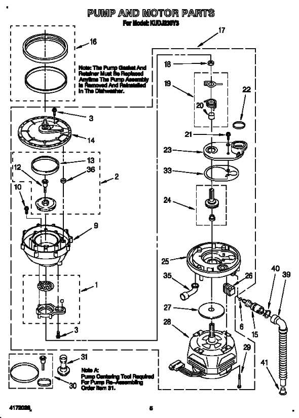
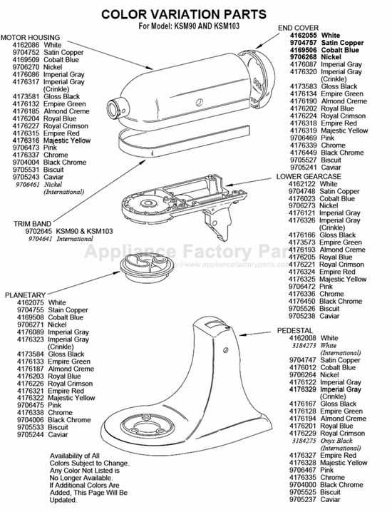
Interpreting a schematic is crucial for understanding the layout and function of various components within an appliance. These visual guides represent the relationships between each element, making it easier to identify and troubleshoot issues. In this section, we will explore how to properly read and interpret the detailed illustration of the device.
Understanding the Symbols and Labels
Each component in the schematic is represented by specific symbols or drawings. These symbols help to distinguish one part from another and provide clarity about their functions. Labels are usually attached to each element, indicating either the part number, function, or position within the device.
- Parts Position: A number or letter typically indicates the location of each component within the assembly.
- Function Descriptions: These notes clarify the role of each part in the system’s operation.
- Connection Lines: Lines show how components interact, typically representing wiring, movement, or mechanical connections.
Following the Flow of Components

Once the parts and their labels are understood, the next step is to follow how they work together. The schematic will often show the flow of energy, motion, or signal between different elements. By tracing these lines, you can identify how each component interacts and where issues may arise.
- Start from the central motor or power source, which is typically shown at the center of the schematic.
- Trace the flow to the key components like gears, attachments, and control switches.
- Identify any common points where parts may overlap or interact to troubleshoot or repair effectively.