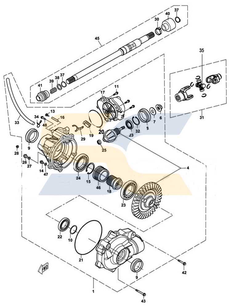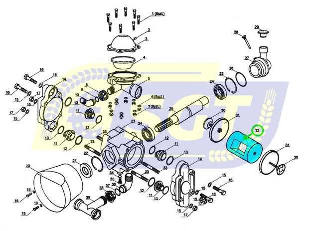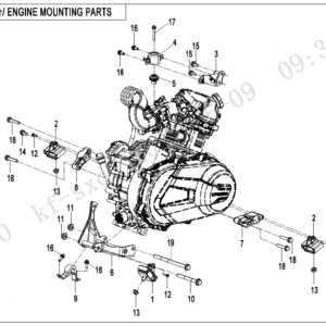
When working on machinery, having a clear view of its individual parts and how they fit together is essential. This section aims to provide a thorough breakdown of how to navigate through the detailed illustrations that represent the various components of a vehicle. Understanding these visuals is a crucial step for anyone performing maintenance or repairs.
The focus here is to simplify the process of interpreting these detailed representations, ensuring that users can easily identify each piece. By becoming familiar with the layout and structure, even the most complex systems become more approachable. Whether you are a seasoned professional or a beginner, this guide will enhance your ability to handle equipment maintenance effectively.
Understanding Massimo Parts Diagram
Grasping the layout of a vehicle’s internal structure is crucial for anyone working with machinery. A detailed illustration of components is an essential tool that helps to identify and comprehend the relationship between different sections of the equipment. These guides are designed to make complex systems more understandable and accessible for maintenance or repair tasks.
Key Features of Component Illustrations
The visual guide breaks down the various elements of the machine into understandable parts, showcasing how each element fits into the overall structure. It is organized in a way that allows for easy identification of individual pieces, making troubleshooting and maintenance much simpler.
How to Effectively Use the Visual Guide
Learning how to read and utilize these schematics is a skill that can be developed over time. Understanding the symbols, connections, and arrangement will help in diagnosing issues, performing upgrades, or replacing components. With experience, interpreting these guides becomes second nature, enabling efficient repairs and servicing.
How to Read the Parts Breakdown

To work efficiently with complex machinery, understanding the layout of the components is essential. A visual representation of the internal structure can provide valuable insights, but knowing how to read and interpret it correctly is key. This section will guide you through the process of understanding these detailed charts to make repairs or maintenance tasks easier.
Here are some key elements to focus on when interpreting these schematics:
- Symbols – Different symbols represent specific components, such as screws, bolts, and gears. Familiarizing yourself with these is crucial for identifying the parts you need to work with.
- Connections – Lines or arrows often indicate how various parts are connected. Understanding these relationships can help you determine how one piece interacts with another.
- Labels and Numbers – Each element is typically labeled with a number or code. Cross-referencing these with a parts list will help you identify the exact component in question.
- Grouping – Components are often grouped based on their function or location in the machine. Recognizing these groupings can make it easier to locate the area you’re working on.
By paying attention to these elements, you can develop a better understanding of the equipment, ensuring that each step of your maintenance or repair process is performed accurately and efficiently.
Key Components in Massimo Diagrams

When examining a detailed breakdown of a vehicle’s structure, it’s important to understand the primary elements that are often highlighted in these illustrations. Each section typically represents a group of interconnected components essential to the functionality of the machine. Recognizing these core parts will aid in performing accurate diagnostics and repairs.
The most critical sections usually include power transmission elements, structural supports, and various operational mechanisms. These components work together to ensure smooth operation, and identifying them can help in troubleshooting or when ordering replacement parts. Understanding the layout and function of each key component is essential for both basic maintenance and more in-depth repairs.