When it comes to maintaining your boat’s engine, a clear understanding of its various components is crucial. Each part plays a vital role in ensuring smooth operation and longevity. Identifying the right components and knowing their function is the first step toward proper care and repair.
Detailed visuals and schematics can be invaluable tools for both beginners and seasoned technicians. They offer a clear representation of how different elements fit together and interact. By studying these resources, boat owners can make informed decisions on maintenance, troubleshooting, and upgrades.
Learning to read and interpret these visual guides helps simplify complex tasks and promotes efficiency. Whether you’re replacing worn parts or conducting regular checks, this knowledge will enhance your overall boating experience.
Understanding Boat Engine Components

For any boat owner or technician, familiarizing oneself with the engine’s essential components is a key step in ensuring proper maintenance and repair. Each element within the power system works together to support the overall functionality, with specific tasks assigned to various parts, from the cooling system to the propulsion components.
Recognizing the structure and role of these individual components is crucial for diagnosing issues or performing regular servicing. The understanding of their layout and connections allows for better decision-making when dealing with troubleshooting, replacements, or adjustments.
By gaining insights into how the various pieces function and interconnect, boat owners can optimize their maintenance routine and extend the lifespan of their engine system. Proper knowledge equips individuals to handle any situation, whether it’s routine upkeep or more complex repair tasks.
Identifying Key Components in the Visual Guide
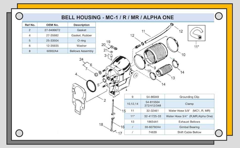
Accurate identification of the critical elements within your engine system is essential for effective maintenance. The guide provides a clear visual reference to help you locate and understand the function of each part, enabling a more efficient repair process. By recognizing the key sections, you can better assess the overall condition and pinpoint areas requiring attention.
Each part is represented with precision, showing its position relative to others, which helps in understanding how the entire mechanism works as a cohesive unit. Knowing the placement and function of each component allows for easier diagnosis of performance issues and smoother replacement procedures.
When working with such guides, it’s important to focus on the components that have the greatest impact on the engine’s operation. Understanding their purpose not only aids in quick repairs but also ensures you are handling the correct parts for replacement or adjustment.
How to Use the Visual Guide for Maintenance
Utilizing a visual reference for engine maintenance is a powerful way to streamline the process and ensure accuracy. By studying the layout, you can easily pinpoint the components that need inspection, adjustment, or replacement. This guide serves as a valuable tool in diagnosing issues and understanding the sequence of tasks involved in upkeep.
When using the visual guide, focus on the areas that are most susceptible to wear and tear, such as the cooling system and moving parts. Knowing where these components are located helps you perform preventive checks and identify potential problems early. This method allows for timely intervention, reducing the likelihood of major breakdowns.
Integrating this guide into your maintenance routine not only improves efficiency but also promotes a deeper understanding of the engine’s functionality. By following the correct steps and focusing on the key elements, you can ensure optimal performance and extend the lifespan of your system.